Motion Study: SolidWorks
Solidworks Motion Study
EnVision Maker Studio
1.1 Introduction:
Motion studies are graphical simulations of motion for assembly models. You can use Solidworks mates in an assembly to restrict the motion of components in an assembly when you model motion. Motion studies in Solidworks do not change the properties of an assembly model. Instead, if changes are made to the assembly after the creation of the motion study, the software will automatically update the study and reveal any possible conflicts.
1.2 MotionManager:
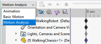
The MotionManager is where you can find all of the core Solidworks tools used for motion analysis: Animation, Basic Motion, and Motion Analysis.

This toolbar is by default found at the bottom of the screen, however, if you do not see anything there you may have to enable the add-in in the settings. To do this, go to the top of the screen and click on the settings icon and click “Add-ins” from the pull-down menu.

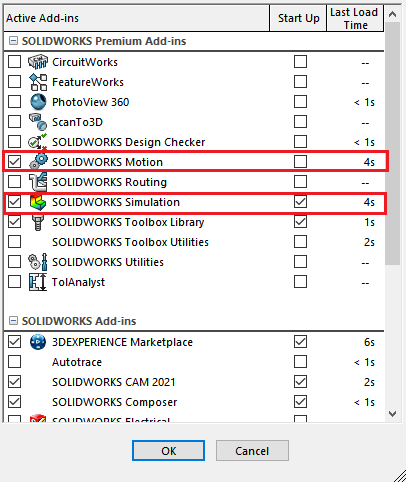
From the “Add-ins” menu ensure that “SOLIDWORKS Motion” and “SOLIDWORKS Simulation” are checked before clicking on “OK”.
Animation
2.1 Animation Wizard:
The Animation Wizard is a quick and easy way to create simple animations of the current assembly. This does not include the movement of parts defined by mates, rather it generates a simple rotation of the entire assembly based on the current camera position.

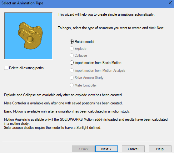
In the first pop-up window select “Rotate Model” and click Next.
The second pop-up window will ask you which direction to rate in, how many rotations, and which original axis you would like to rotate about (typically choose Y-axis).

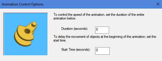
The last pop-up menu will ask you when to begin the rotation and how long the rotation will last.
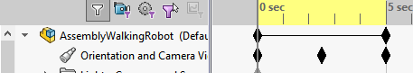
The Animation Wizard then generates camera keyframes marked as diamonds in the MotionManager. Before starting the animation, ensure the grey bar is at the “0 sec” mark. Clicking the play button will start the animation.
2.2 More on Camera Keyframes:
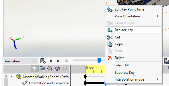
Instead of using the Animation Wizard to make keyframes, we can make our own camera keyframes based on our views in the Solidworks assembly window. First, find a view in your Assembly window that you want to begin your animation on. Next, locate and right-click on the first keyframe next to “Orientation and Camera Views”. Click on “Replace Key”, this changes the first camera view of the animation to be your prefered starting view. Until you replace this key again, every time you start the animation from the beginning it will return to this camera view.

Bounce Animation:
The easiest way to make camera keyframes is by click-holding onto the first keyframe and dragging it along the timeline. This makes a copy of the original camera view but that can be changed by clicking “Replace Key”. First, create two copies of the first keyframe and place them along the timeline like so:
To create the Bounce animation, move the grey bar on top of the middle keyframe. Next, move the assembly to a second position that is different from the first. Finally right click on the middle keyframe and select “Replace Key”.
This will create a Bounce animation where the camera moves from Position 1 to Position 2 and then back to Position 1. You can also move around the keyframes to change the speed of the Bounce Animation to how you see fit.
2.3 Motors:
Motors can be used to manipulate a component for a certain amount of time as defined by a mate. In this tutorial, you will animate a rotation along an axis but be aware that you can also create a linear oscillation along an edge/axis as well.
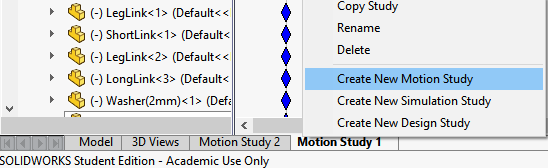
Note: Create a new motion study quickly by right-clicking your current “Motion Study” tab at the bottom of the screen and selecting “Create New Motion Study”
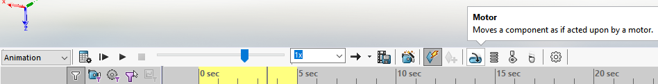
To create a Rotary Motor first click on a circular edge to establish what direction and part you want to move. The assembly mates will update based on the properties of the motor. Ensure that the motor you create has a red arrow indicating the direction of the motor which can be changed.

The motion box gives you many options to control the motor including distance, oscillation, segments, etc. For this specific example, I will be using the Constant Speed option which will rotate the motor in one direction at 25 RPM. Clicking the graph at the bottom of the box allows you to more closely analyze the motion.
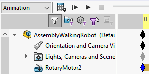
After clicking the green checkmark, you will see a new Motion Study element created on top of all the model features. To see the motor move click the play button and allow Motion Study to calculate the frames.
Note: You can recalculate frames whenever in motion study by clicking the Calculator Icon:
Animation Framerate
Solidworks automatically sets the framerate of the animations to 8 FPS which creates a rather choppy viewing experience. Change this to a higher number in the animation settings menu
Basic Motion
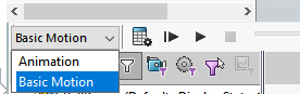
Basic Motion is different from Animation as it takes into account the mass, inertia, gravity, and contacts to calculate motion more accurately. Animation simply uses interpolation provided by keyframes whereas Basic Motion is capable of creating more complex real-world simulations. Change to “Basic Motion” in the Motion Manager bar at the bottom of the screen.
This tutorial will be following a Ball and Slide Assembly which you should download and try yourself.
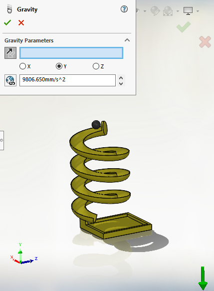
3.1 Gravity:
Gravity is a key tool for simulating motion in an assembly. Go to the right side of the Motion Manager bar and click on the falling apple symbol.

Next, you have the option to choose the direction and magnitude of gravity in your assembly either based on a chosen edge/axis or one of the global axes. In this example, we will choose the global Y-axis and ensure the green arrow is pointed down.
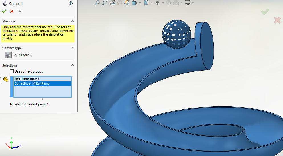
3.2 Contacts:
Defining contact points/surfaces in a Motion Study is crucial to simulating real-world interactions. In Basic Motion, this works well with smooth surfaces that do not have many complicated rough edges. This button is just left of the gravity button.

Note: You can create contact groups that simulate interactions between different sets of objects. In this example, however, we will only be using one set of contacts.
Clicking on parts will highlight the entire surface and create contacts.
Clicking on the Calculate button will run the simulation (Be sure to change the framerate to smooth out the animation)

Motion Analysis
Motion analysis is a more intensive version of basic motion as it allows you to more closely analyze the effects of motion in an assembly. Just like Basic Motion, Motion Analysis uses the mates and rigid bodies defined in your assembly to calculate motion. However, motion analysis offers you more tools for analyzing the data that results from this motion so that the engineer can better understand the dynamic system. In this tutorial, we will cover Trace Paths and Result Plots which are important steps in the Walking Robot project.
4.1 Trace Paths
The Trace Paths function allows you to pick any point on your assembly to trace a path during a motion study. This is helpful especially when creating linkages that have complex paths of motion that you want to analyze.
To start, create a new motion study by right-clicking the current motion study tab at the bottom of the window and selecting "create new motion study".
In the new motion study ensure you select "Motion Analysis" in the top left corner of the manager tab.
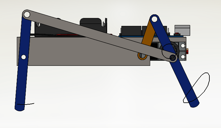
Create a new rotary motor by following the same steps as the Animation study so you have a result that looks like this:
For the purposes of this tutorial, we will only be analyzing one side of the robot since it is symmetrical. Now we will create a new trace path by using the Results and Plots tool in the motion manager.

In the Result section select Displacement/Velocity/Acceleration and then Trace Path.
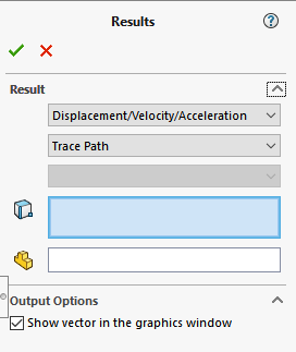
Next, select a point on your moving assembly where you want to trace a path. If you select an edge this will not work since a path cannot be traced for an infinite amount of specified points, however, if you select a curved edge SolidWorks will automatically attach the tracepoint to the radial center of the curve.
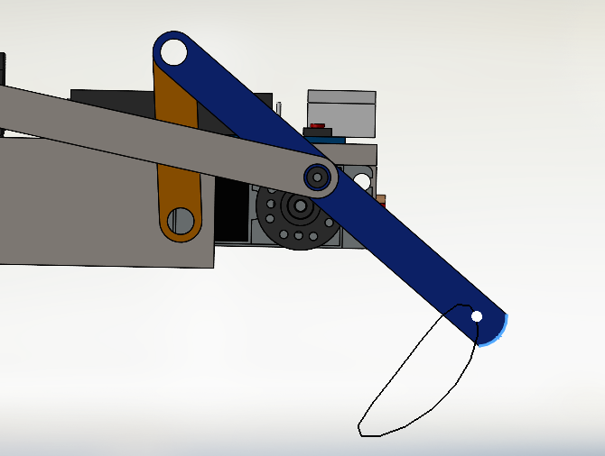
Repeat this step for the other leg:
Use these trace paths to analyze the motion of the legs and optimize the link lengths.
4.2 Motor Torque Analysis
In a moving assembly such as this one, one may find it useful to analyze the load being applied by the motor to ensure the amount of torque is realistic.
Once again click on the "Results and Plots" button. This time in the Results section select "Forces" then select "Motor Torque" and lastly select "Magnitude". This analysis will be applied to the Rotary Motor just created so be sure to select it from the left side of the motion manager bar.
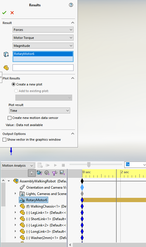
This will generate a detailed plot of the motor torque. The reason for this analysis is to determine whether or not the magnitude of the motor torque required for the assembly is greater than what the actual motor can supply. In this case, the motor torque is just fine as the maximum magnitude the assembly ever reaches is just 0.31 newton-mm (1 newton-mm = 0.001 newton-m) and the motor being used in the actual robot is rated for 10 kg-cm (9.8 newton-m).