Schematic Design
1.1 Introduction
Physical circuits on a board are first built on paper in the form of a schematic diagram. Circuit design typically begins with a schematic, where components are chosen, nets are created, and the flow of signals determined. The PCB is then created by using the schematic as its primary reference. Building the PCB from the schematic and working with the two in tandem not only simplifies PCB layout, but also allows for better error checking, component selection, and overall workflow.
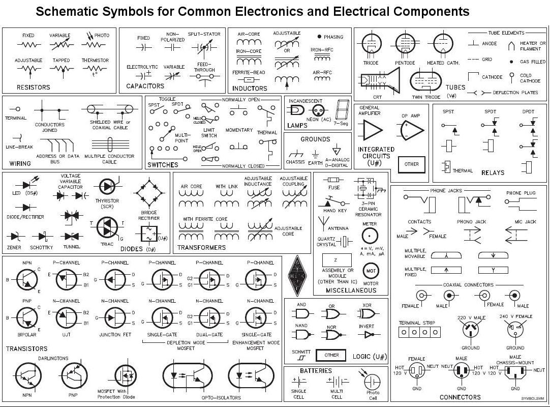
1.2 Electrical Components
A component is any part or piece that is attached to a circuit board. This includes:
- Resistors
- Capacitors
- Light Emitting Diode (LED)
- Transistors
- Inductors
- Integrated Circuit (IC)
- Circuit Breaker
- Fuse
- Switch
- Transformer
- Electrical Wires & Power Cables
- Battery
- Relay
- Motor
( https://www.dfliq.net/blog/the-basics-of-electrical-components/ )
1.3 Schematic Symbols

1.4 Basic Schematic Concepts
When you create a schematic, you are developing all of the nets, or connections, that will eventually exist on your circuit board. Every single pin on every single component will be connected to another pin, a ground plane, or a copper island ( a visible piece of copper on the top of the board that is not associated with a net ), and the schematic determines where all of those connections are.