Finite Element Analysis: SolidWorks
Finite Element Analysis: SolidWorks
1.1 Quick Introduction:
Finite Element Analysis (FEA) is a powerful tool used by engineers to predict how parts and assemblies react to forces: heat, fluid flow, vibration, etc. Computer software such as SolidWorks, FEMAP, ANSYS, and Matlab use numerical analysis to create a general 3D mesh on the surface of the product and calculate stresses based on user-defined materials and forces.
Note: Solidworks is not the most precise FEA software to use for engineering purposes, however, it is still accurate and is simple to use. Solidworks comes with a Simulation Advisor which is a helpful tool that walks you through the process.
1.2 Definitions and The Process:
Definitions:
Finite Elements: Discrete amount of shapes used to calculate the deformation of a part. They are connected together at nodes and are typically triangle shaped in SolidWorks.
Mesh: The culmination of all connected finite elements of a part perfectly dispered over the surface area of the part. A good mesh can determine the accuracy of your FEA.
Von Mises Stress: Used to predict yielding from external stresses. Typically represented by red colors in FEA, yielding stress can occur at several different locations on a part depending on the load magnitude, direction, and location.
The process for FEA goes as follows;
Define the reason for the study. You could possibly be concerned with:
- Excessive compression/expansion/deformation
- Temperatures
- Loading cycles
Define the material being used
Create fixed geometries at certain locations
Apply loads at certain locations
Generate a mesh to your liking
Run study
2.1 Creating a Static Study in SolidWorks
The rest of this tutorial will be explained using the part shown below:

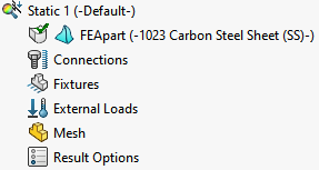
Start by going to the “Simulation” tab at the top of the screen and clicking “New Study”

In the Study, menu ensure that you check the Static box under General Simulation and click the green checkmark.

2.2 Applying Materials
After you have made a new Study, click on Apply Material at the top of the screen.

For this tutorial. we will be using 1023 Carbon Steel. Be aware that most materials you will ever need to analyze will be in this material library, however, you can add your own material be clicking the “Add…” button. When you’re done click “Apply”, this may slightly change the appearance of the material.

You can confirm this by checking the features menu on the right side of the screen
2.3 Creating Fixed Geometries
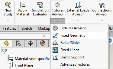
Fixed Geometries can be points, edges, or faces on a part that will not move in a specified direction. In order to run a FEA you need to have at lease one point of fixed geometry. To do this click on the “Fixtures Advisor” in the top bar and then select “Fixed Geometry”.
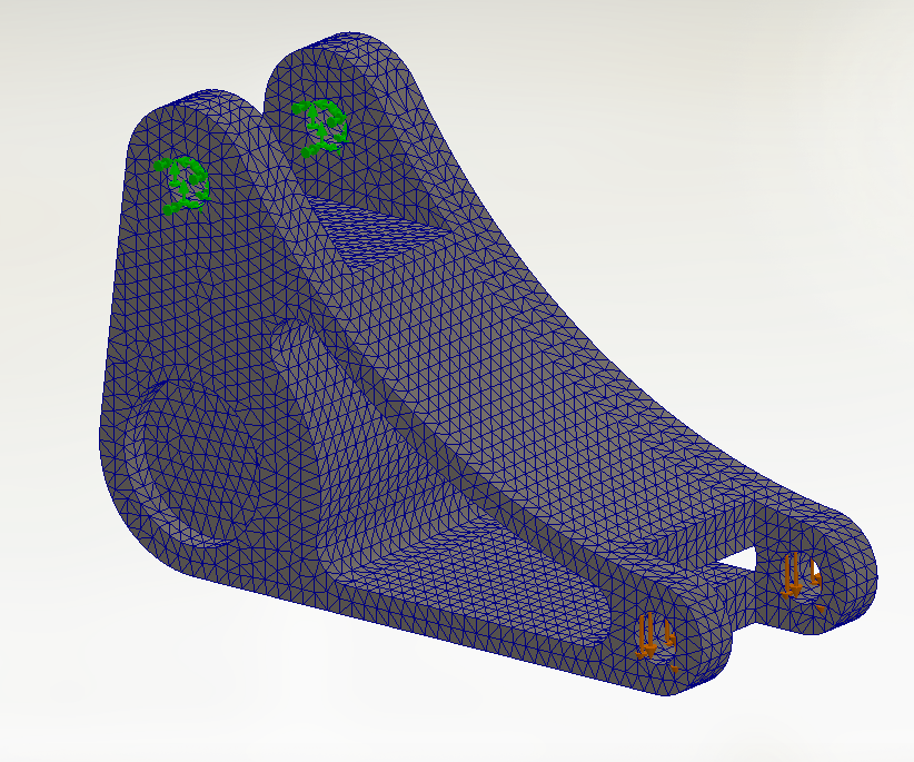
In this instance, we will create a fixed geometry at the faces shown below, note that fixed geometries are denoted by green arrows in SolidWorks.

2.4 Applying External Forces
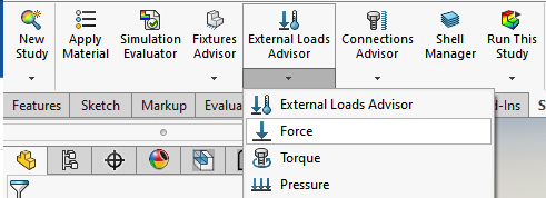
External Forces can also be applied to points, edges, and faces on a part. Do this by going to the top bar and selecting “External Loads Advisor” and then clicking on “Force”.
In this instance, we will apply loads at the two faces shown below (Solidworks automatically points forces in the direction normal to the face of the part).

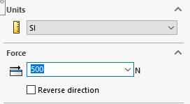
To change the direction of the force being applied, click the “Selected Direction” bubble and then select an axis or edge to bind it to. In this case, it will be in the vertical direction (Y-axis) so I clicked on a nearby edge that was also in the vertical direction.

Solidworks also defaults to 1N of force but in this study the part will be under 500 N. (Proceed by clicking the green check mark)
2.5 Generating a Mesh
Solidworks automatically creates a mesh before a Static study is run. However you may want to view and change the resolution of this mesh in order to generate more accurate results with your study. Do this by going to “Run This Study” and clicking on “Create Mesh”.

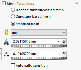
This opens up a window that gives you options on how you want to create your mesh. Mesh Density changes the size of individual triangles depending on how Coarse or Fine you want your elements to be. In this case, we want the finest possible mesh.

Mesh Parameters, when checked, allows you to manually input the maximum and minimum element sizes and gives you options for mesh curvatures. In this case we will just be using the “Standard mesh” option.
Clicking the green check mark will tell Solidworks to create the modified mesh based on our new settings and parameters. The resulting mesh should look like this:
2.6 Running the Study and Post Analysis
The final step in the process is to run the study by clicking “Run This Study” in the top bar. Allow Solidworks some time to generate the results.

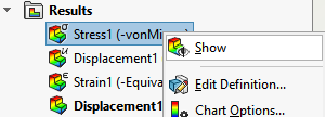
Your part should now be visually deformed and new results should pop up in the feature menu. Solidworks automatically gives results for vonMises Stress, Displacement, and Strain.

By right clicking on any of the results and clicking “Show”, Solidworks adds color to your part and highlights important areas of change. (This can also be done with a double-click)

Note: The top left corner of the viewing space shows a “Deformation scale” number. This value is multiplied by the true deformation amount so that it is easier to see a difference in the model.
Another Note: According to the von Mises stress chart here, this part has a Yield Strength of 2.827e+08 [N/m^2] and it looks like no sections of the part reach this limit (indicated in red) so, most likely, no yielding will occur under a load of 500 N based on this simple analysis.
Deformation Scaling
Changing the scale of deformation is simple. Right click wanted result and go to “Edit Definition”. In the Plot menu, head to the “Deformed shape” section, click “User Defined”, and input a deformation scale number below

Creating a Deformation Animation
Sometimes it may be useful to see how your part will deform using a moving picture. To create an animation, right click on “Stress1” under “Results” and click on “Animate”.
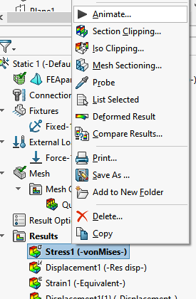
This automatically creates an animation with a default of 5 frames. To make the animation smoother, stop the playback and type in a larger amount like 30. This will take longer to calculate but you will have a much smoother result.
