Walking Robot
By Blake Iwaisako
Walking linkage robots are very cool machines that simulate natural motion. However, they can be tedious to engineer as they often have many moving parts that must fit perfectly into the design. Often they go through many periods of trial and error before they are able to walk properly.
If you want to build one of these machines, it is crucial that you understand how the mechanisms operate and how to simulate them. Motion simulations allow you to understand the movement of your machine and calibrate how it interacts with the ground.
For this project, you will design a robot that walks around using a 4-bar linkage for legs. You will be required to:
- Design a working chassis to house all electronic components in SolidWorks.
- Manufacture and/or source all parts needed (nuts, bolts, motors, microcontrollers, etc.).
- Create a Motion Study in SolidWorks that theoretically proves your design will work as intended.
- Assemble the robot and write code to make it run.
Brief on 4-bar Linkages
4-bar linkages are a very useful mechanism used in mechanical engineering that consists of four rods connected by pins. These mechanisms convert rotational motion into a rocking motion which can be very useful in robotic arms, clamping mechanisms, animatronics etc.
Gif Source: mecademie on YouTube
When designing 4-bar linkages engineers analyze different rod lengths in order to find an ideal output motion. One can calculate the exact range of motion when given each rod length and tools like SolidWorks allow you to simulate a path for every point in the system.
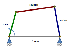
The simplest 4-bar linkage can be seen below, called a crank-rocker mechanism. Two of the pin joints are mounted in all directions, unable to move at all. The crank arm is the input rod that controls the entire system and is what's typically driven by a motor. The coupler arm simply connects the input crank to the output rocker arm but is crucial in determining the range of motion of the entire mechanism. The output rocker arm is always longer than or equal to the length of the crank arm.
Image Source: Wikipedia
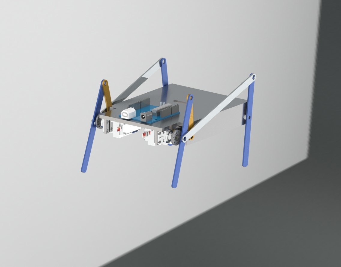
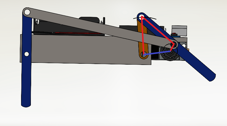
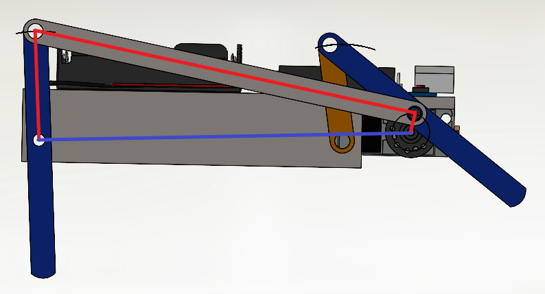
In this robot, you may notice that there are actually two crank-rocker mechanisms at work:
Design a Chassis
You can design this robot with one or two continuous rotation motors. In this tutorial we will be following a robot that has two high torque continuous rotation servo motors.
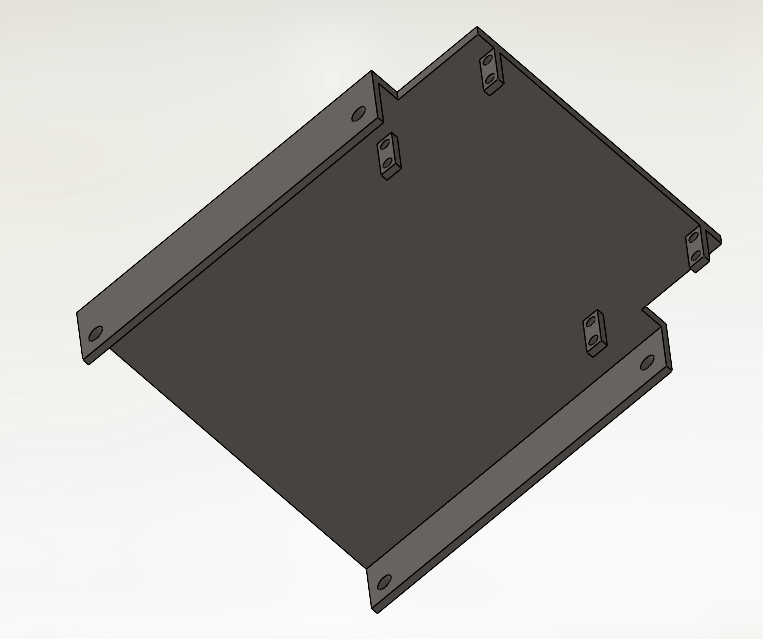
Without dimensions, here is an example of a semi-working chassis:
Design the Links
For this project you will need a total of three different linkages of varying lengths as shown:
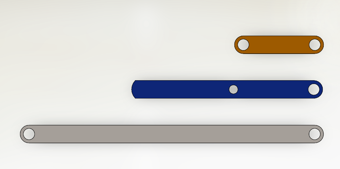
The short orange link connects the top of the blue leg shaft to the chassis. The middle hole on the blue leg connects directly to the servo motor wheel which acts as the crank. Lastly, the link acts as the coupler. Intentionally dimensions were left out since your model will most likely be different and you should play around with the linkage lengths in order to figure out what dimensions work best.
Create a Motion Study in SolidWorks
Head to: Tutorials -> Motion Study: SolidWorks and walk through the tutorial. You will learn to create camera keyframes, animations, basic motors, physics simulations, and motion analyses. You should at least read through the entire tutorial and try out some of the examples.
For the purposes of this project, you should complete the Animation and Motion Analysis sections of the tutorial. The exported animation file and trace path data will be turned in alongside your project.
Putting it all together
Hopefully by now you have completed the motion study tutorial and have a moving animation. Now you need to finish building the actual robot which may be tedious. I would suggest that you laser-cut the leg links as that will be much faster than 3D printing or machining. The chassis will most likely have to be 3D printed depending on how much detail you put into it. Be sure to include a convenient place to store the battery on the robot.