Project l0ckcr4ck3r
By MingWei Yeoh
This is not for the faint of heart. This thing takes long and its hard to get right. Only for the advanced and over achievers.
PCB & Code Files found here.
About the Project
This robot is a true creation of the idea many years ago brought on by Samy Kamkar's robot that "utilized" his algorithm for cracking these combination locks. The entire process works on the majority of locks that don't have much resistance on the dial and usually takes ~40 seconds.

Specifications
The heart of the robot uses a TMC2208 super silent trinamic stepper driver w/ AS5600 mag encoder on the back to turn the lock dial and "feel" for the lock's geometries. A servo with analog output detects when a successful attempt was made to open the lock. Also added functionality which includes a GUI which is an oled + rotarary encoder for user input. The entire assembly is powered by a 12V USB C charger with a fan to cool down the stepper driver.
Challenges
PCB
Due to the sheer complexity of the mechanical aspect, you can just use the PCB files provided.
CAD
Will be doing the CAD from scratch!
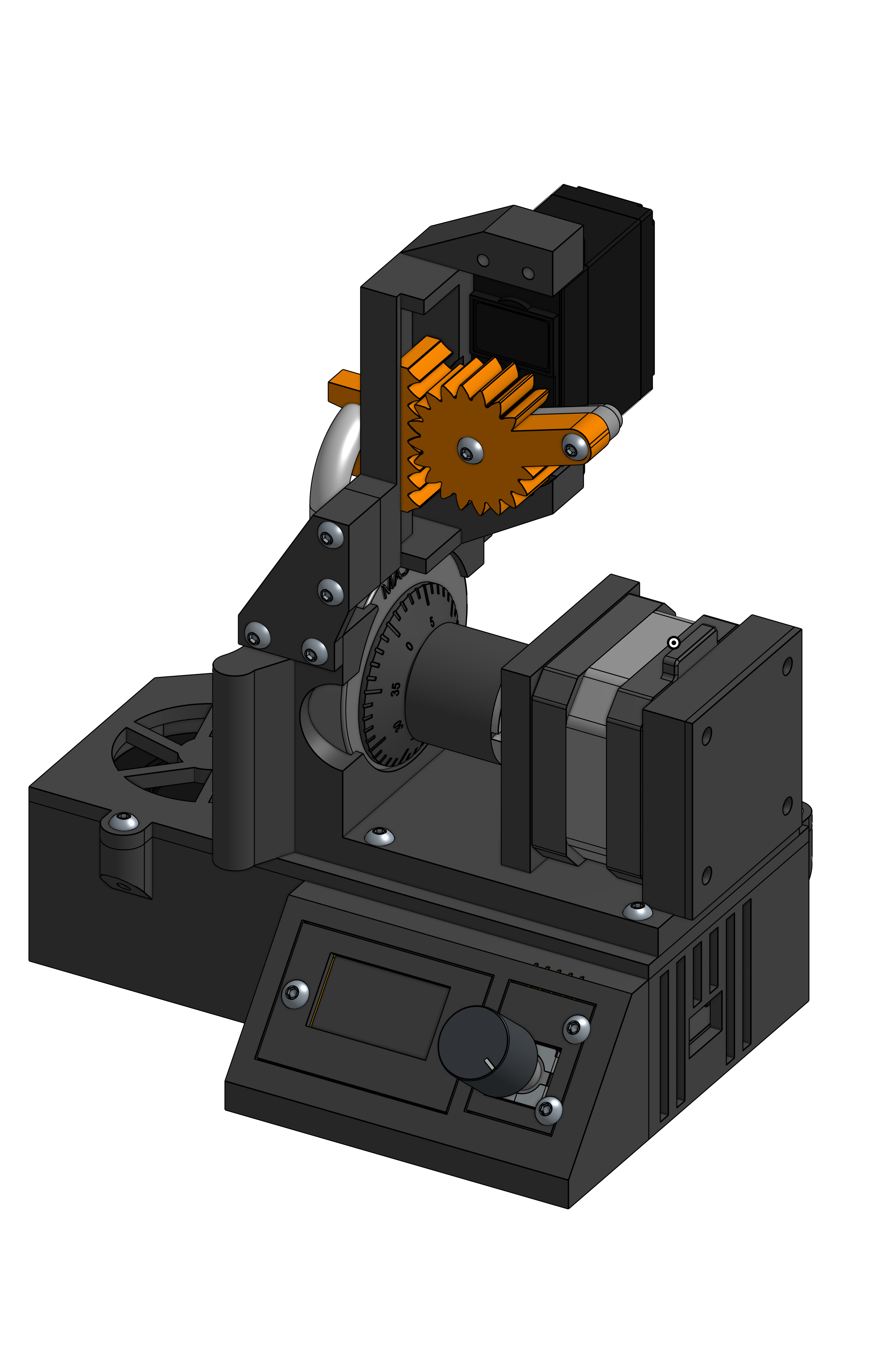
Mine ended up looking like this:
Code
Due to the sheer complexity of the mechanical aspect and that my code is about 800 lines long, you can just use the code provided.
Materials
Mechanical
Electrical
- Arduino Nano
- 10uF Capacitor x2
- Diode
- 5V Regulator
- OLED Display
- Rotary Encoder
- Blower Fan
- USB C 12V
- Power Supply
Background information
This robot takes advantage of Samy Kamkar's exploit. I reccomend watching this video if you are actually going to build this. You absolutely need to understand what the robot is trying to do under the hood or else there's no way you can debug anything.
The plan
First we are going to make the housing for the lock, sensor, and actuators. After that works, then we will make an enclosure for the electronics
Getting Started
This document includes all of the standard content needed. You can either work in Onshape (reccomended) or export the content to use in Solidworks
CAD
Motor -> Lock Dial
Now it is your job to make pieces to hold the motor in place to the lock dial.
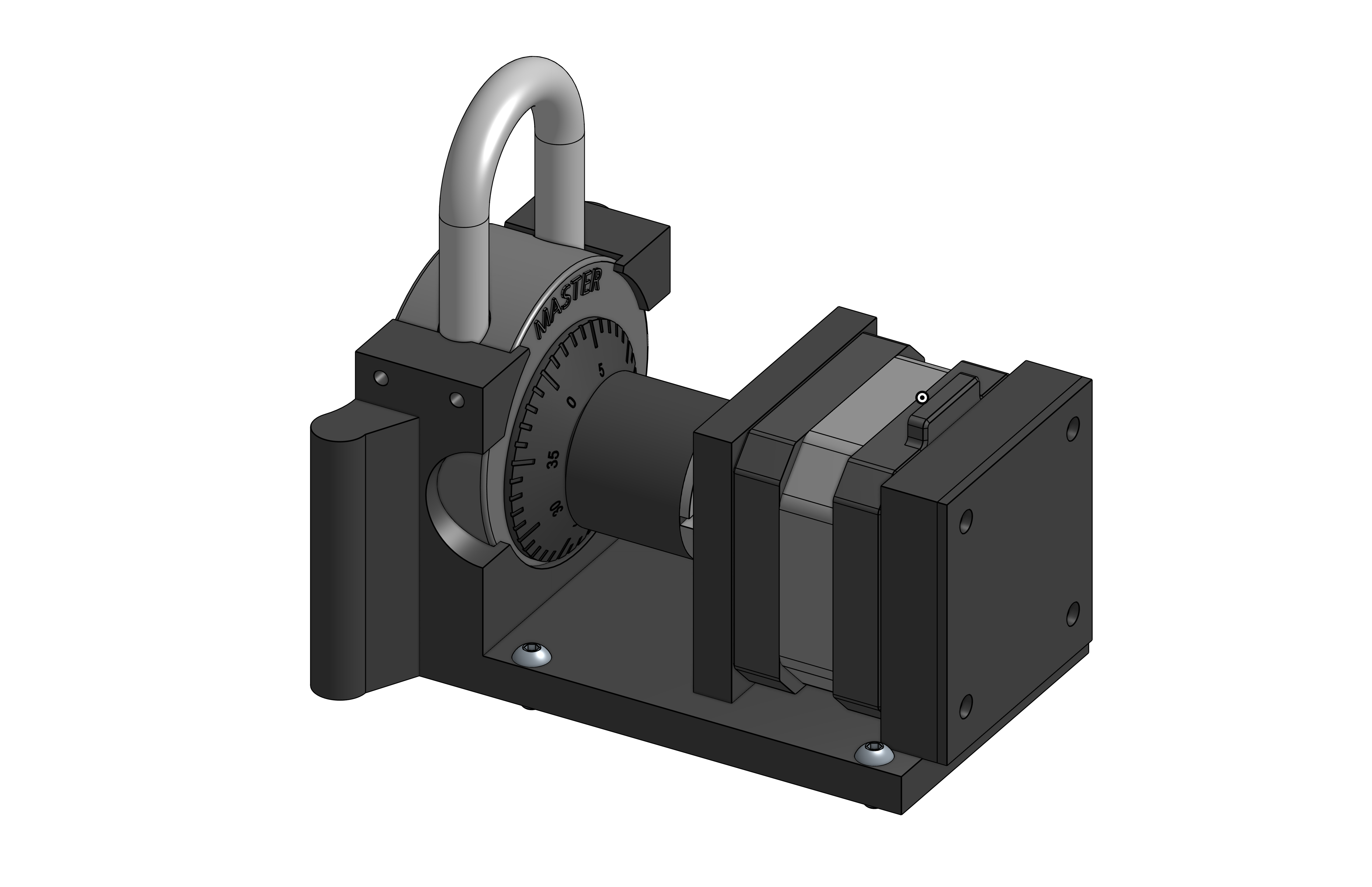
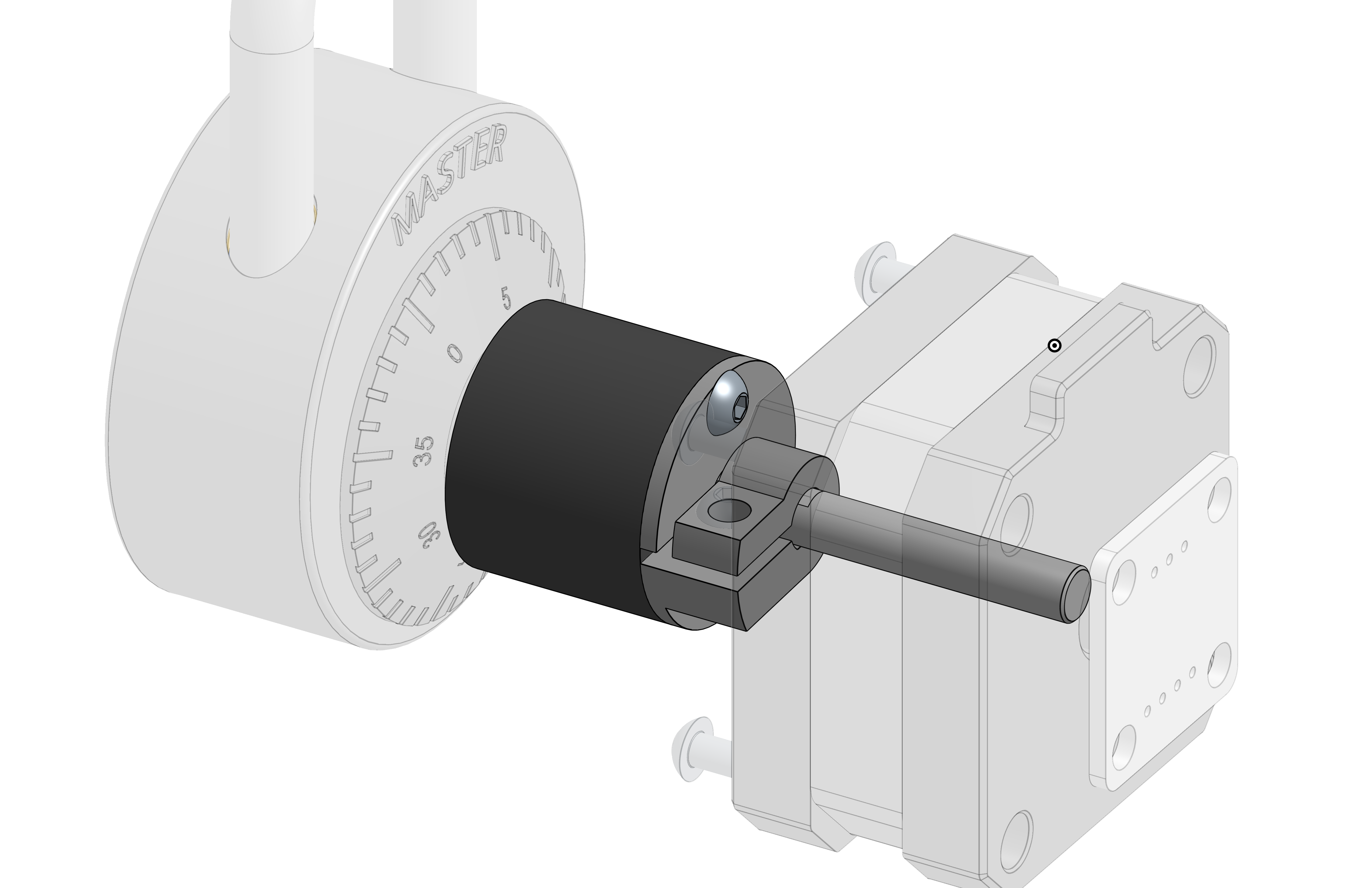
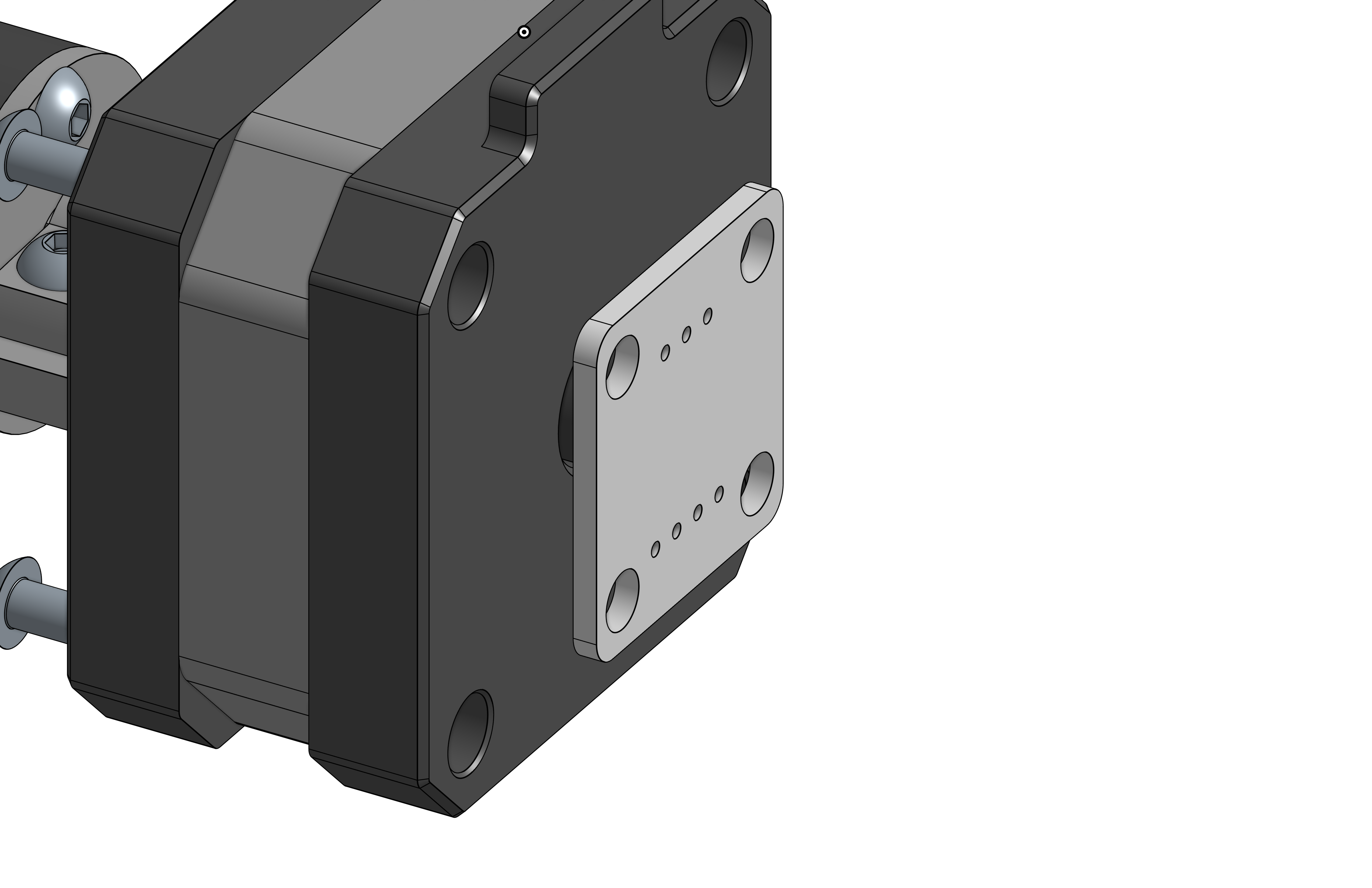
Make a part to hold the lock and the stepper motor in place. Ensure that the stepper motor's shaft is cocentric with the lock dial.
Use the mounting points of the stepper motor to fasten it onto your main part. The lock can be friction fit to the part.
The coupler from the stepper motor shaft to the lock dial has already been provided since it is hard to get the geometry right.
After you have made all the parts, ensure that they work well in an assembly together.
Motor Encoder
Now you need to attach the AS5600 Magnetic encoder to the back of the stepper motor! Make a part that attaches to the back of the motor and then simply have the magnetic encoder screw into that part.
Shackle puller
Next, make a rack and pinion gear that attaches to the servo to pull up (as well as push in) on the shackle. Try to make a design similar to the gif below
Electronics
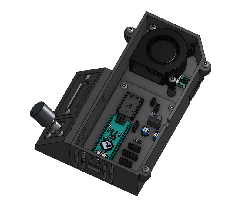
Make an electronics enclosure that has space for the custom PCB, USB C input, and blower fan. Ensure that the blower fan is pointing directly at the stepper driver or else it may overheat.
Make sure to have opening for the usb connections and secure all the components with M3 fasteners.
Then make points to put the OLED display as well as the rotary encoder.
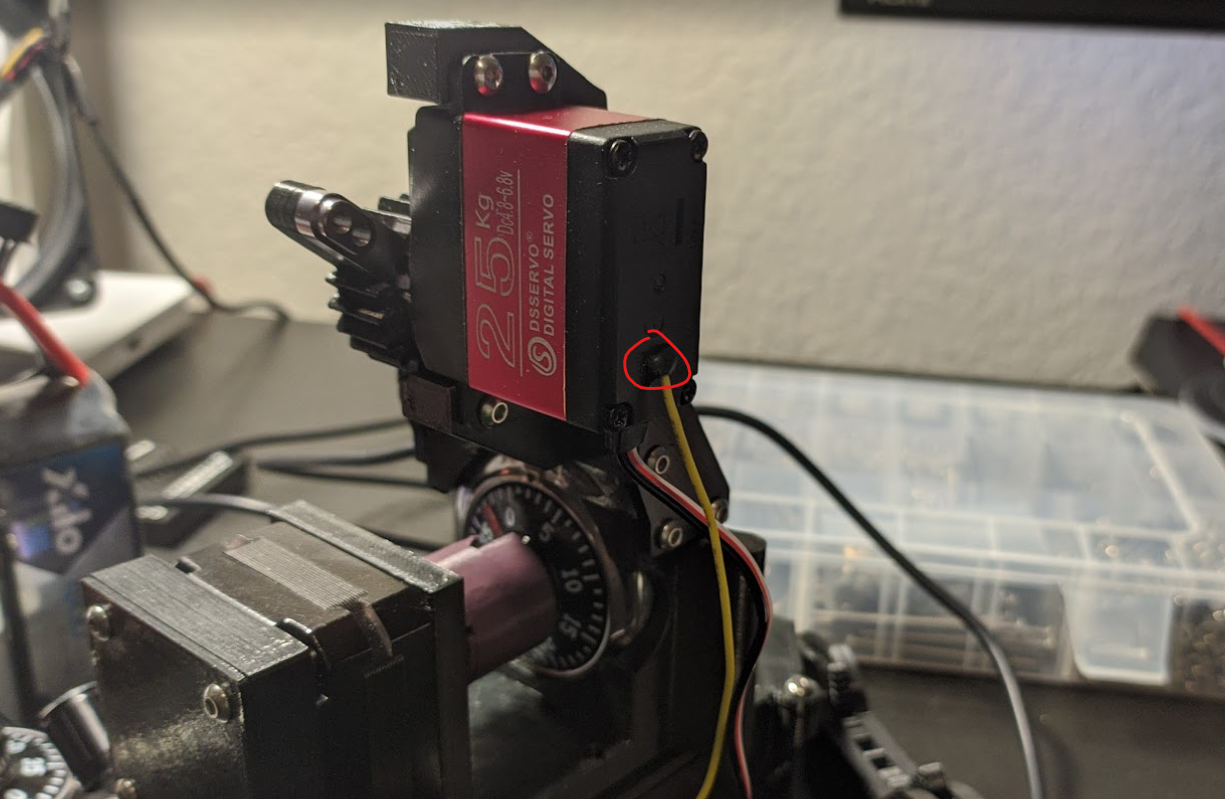
Analog Output Servo modification
In order to determine whether the lock actually opened or not without an extra sensor, we are going to "hack" our servo and turn it into one with an analog feedback.
To do this, you will need to unscrew the servo and solder a wire to the center potentiometer pin on the outside. You can also follow this video on youtube to learn more about the process.
You may have to drill a hole in the casing of the servo in order to have the analog output wire come out of it.
Electronics
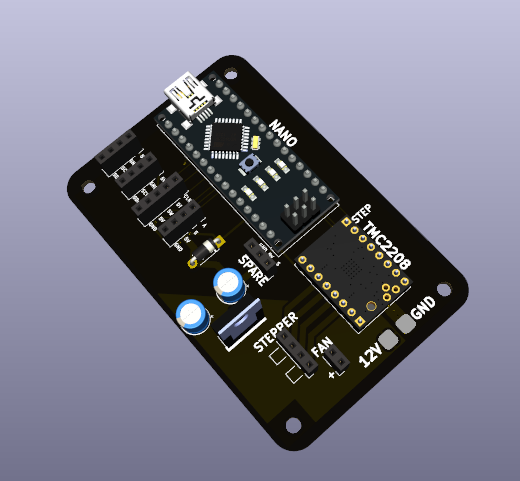
Solder the correct electronic components to the PCB in accordance with the picture below. I would highly reccomend attaching the female dupont pins so that you can easily disconnect things.
Be sure to attach the Input pad to the USB C trigger module with the right polarity!
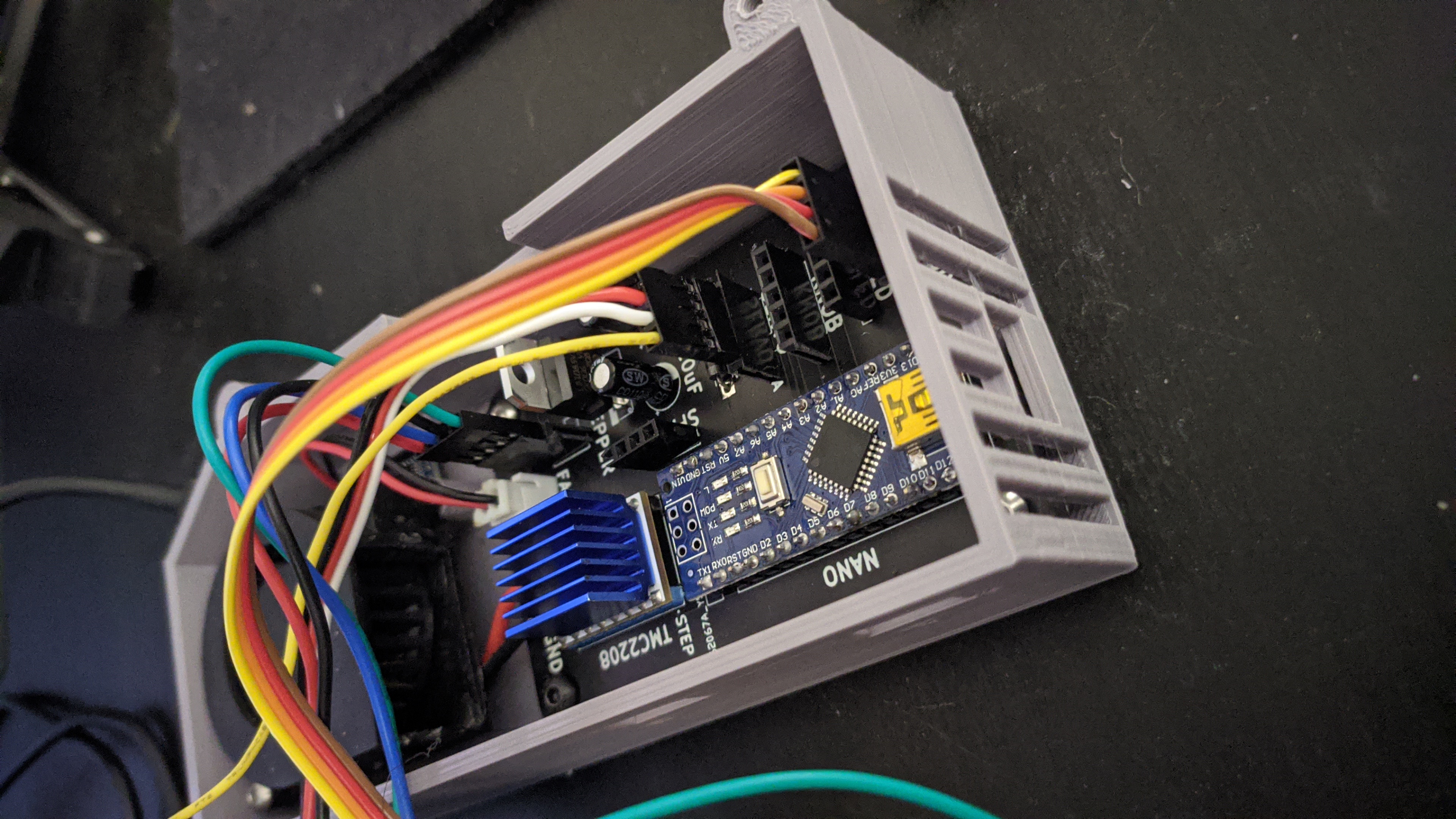
Afterwards, go ahead and wire the stepper motor and the magnetic encoder to their corresponding inputs. Also plug in the servo with it's analog output to the correct port. Be sure to glue the diametric magnet to its mount and glue the mount to the shaft of the stepper motor.
Testing the stepper motor / magnetic encoder
Ensure that the stepper motor works by running a basic Stepper motor sketch. Remeber that the stepper motors are dead silent thanks to the TMC2208 silent stepper driver.
Now make sure that the AS5600 magnetic encoder is reading properly. Run a basic example sketch. It's value should change whenever you rotate the motor.
Testing the servo
Run servo_setup.ino. Try changing the position of the servo by typing a number value between 1000-2000.
Calibration things
Should be done after all the mechanical aspects are finished!
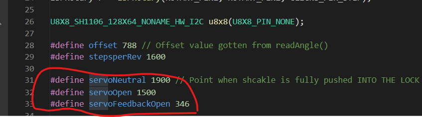
Servo values
Run servo_setup.ino. Try changing the position of the servo by typing a number value between 1000-2000.
Use this script to find the upper and lower bounds that the servo will need to move.
Lower bound - Lock is fully open
Upper bound - Lock is fully closed (shackle fully pushed into the lock)
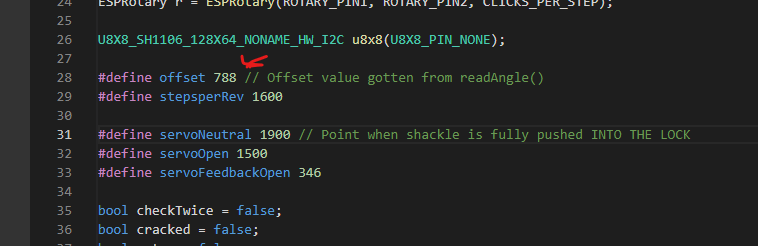
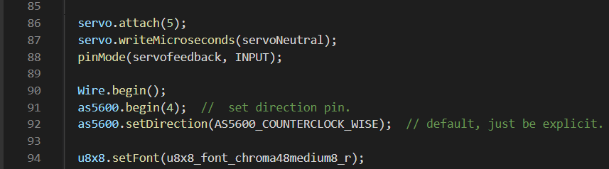
Calibrating magnet offset
Run a AS5600 sketch that runs the readAngle() command.
Set the lock dial to zero and read what the readAngle() command is outputting. Input that value into the offset variable for the combobreaker.ino file
Checking readLockDial()
In combobreaker.ino run the readLockDial() function to determine whether you are correctly reading the current number that the lock is at. If it seems like the numbers are going in the opposite direction when you are rotating the dial, change the setDirection function.
Lock -> Motor coupler
The two bolts that clamp the two motor coupler parts together should be loose. The combination locks have a big amount of play in them and are a little ovalized. The looseness in the system helps to prevent the dial from becoming overconstrained and binding up and certain points in the lock dial.