SimpleSynth Project
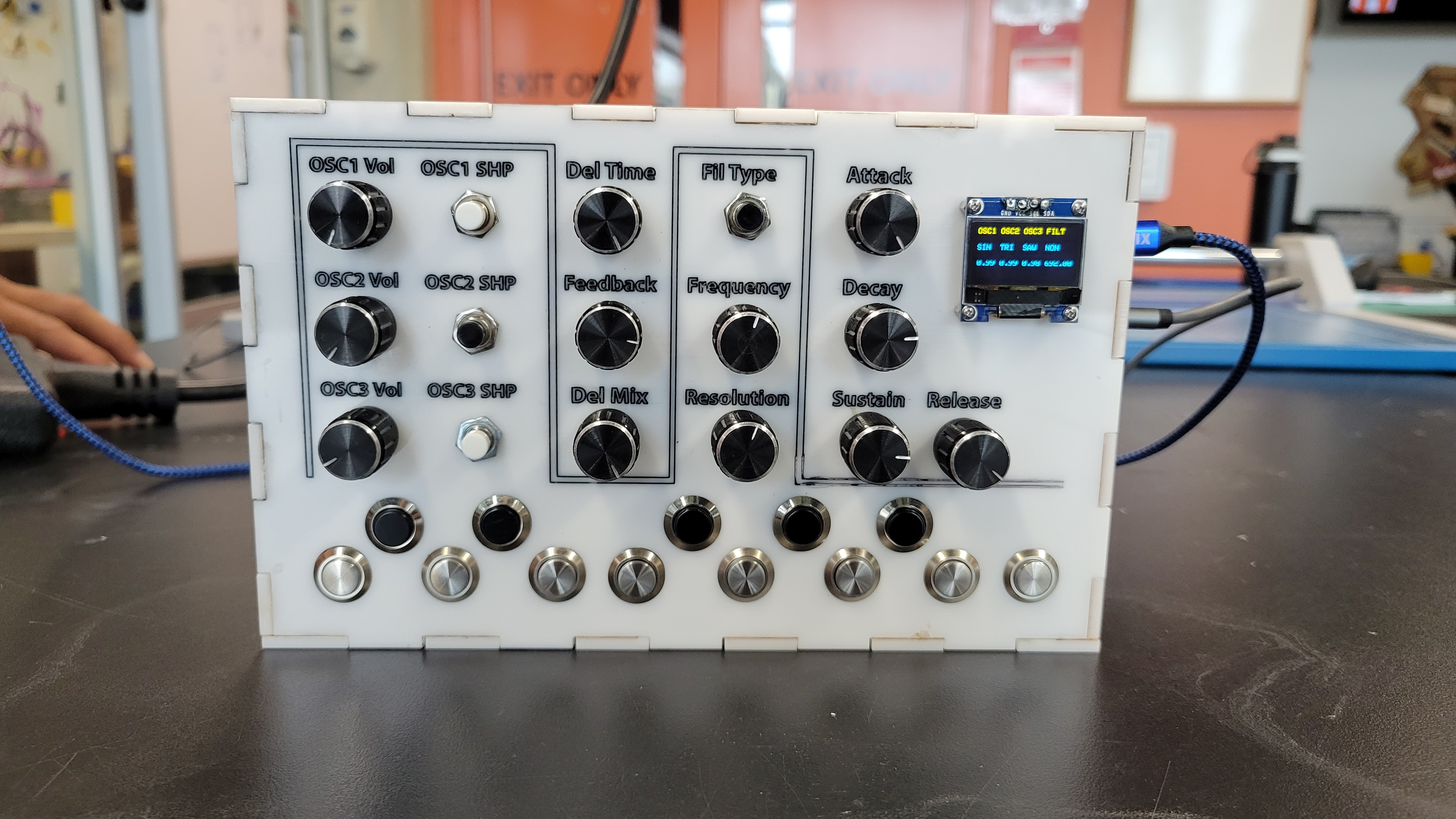
The SimpleSynth is a Teensy-based audio synthesizer. We will be building an expansion board for the Teensy, as well as an enclosure for the boards and controls (switches, buttons, potentiometers, etc…) and then programming the synthesizer using the Arduino IDE and the Audio System Design Tool for the Teensy Audio Library. While the final product represented here is fully functional, it is also very expandable, and users are encouraged to explore ways of doing so by adding various effects, controls, displays, etc…
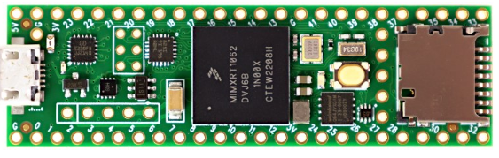
Our Microcontroller of choice for this project is the Teensy 4.1:
https://www.pjrc.com/store/teensy41.html
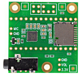
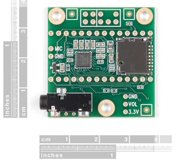
…which we will use with the Teensy Audio Board:
** https://www.pjrc.com/store/teensy3_audio.html**
IMPORTANT: One of the first things we'll need to do is install Teensy in the Arduino IDE. To do so, go here.
The final synthesizer will have the following:
- Full octave ( C - C ) keyboard with polyphonic capability
- 3 oscillators of variable waveshapes
- Digital filter with parameter controls
- Digital delay with parameter controls
In order to build the synthesizer,
- We will create and design our circuit board in Altium Designer
- We will design our enclosure using Adobe Illustrator and Makercase.com
- We will source and purchase parts from Digikey.com
- We will program the synthesizer using the Teesny Audio System Design Tool, the Teensy Audio Library, and Arduino IDE
PART 1: PCB/Schematic Creation
- Create a new project in Altium and call it SimpleSynth
- Add a new schematic document to the project, followed by a new PCB document, both named SimpleSynth
- The primary component of our circuit board will be the Teensy 4.1, so we need to either create our own schematic symbol and footprint, or download one from SnapEDA.com:
- Teensy4.1 Design Files ( I created my own schematic and footprint, so if you download them, yours may look different )
- The next component we’ll need is the Texas Instruments CD74HC4067M, which is a 16-channel Multiplexer/demultiplexer. ( The MUX/DeMUX chip is what we’ll use for the analog control inputs from the potentiometers )
- Unlike the Teensy, we can find this chip by using the Manufacturer Part Search in Altium. Just paste the part number in the search dialog and choose the first part that comes up. ( verify that this is the SMD version of the chip and not the through hole version )
- Now we need an LED and a resistor which will serve as our power indicator. Use the Manufacturer Part Search to find “LED 0805” and “resistor 0805” and place both components. Change the resistor’s comment to “560R” (560 Ohms)
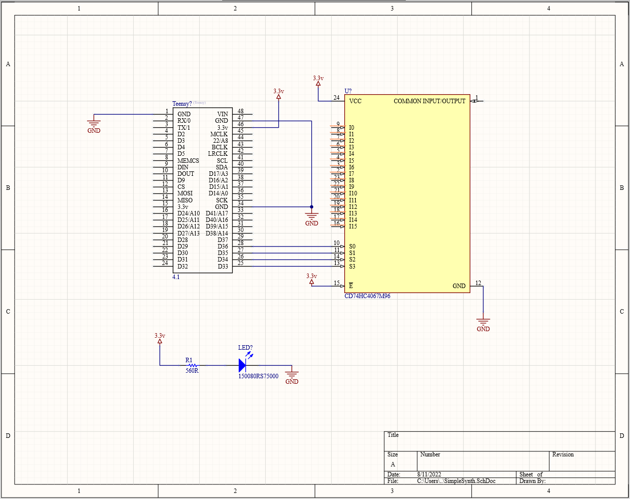
- Add a GND port to all GND pins and pin 2 of the LED.
- Connect a Power Port to VCC and 3.3v pins, as well as pin 1 of the resistor. Also connect it to the E pin of the MUX chip.
- Connect Teensy pins D36, D35, D34, D33 to S0, S1, S2, S3 respectively on the MUX.
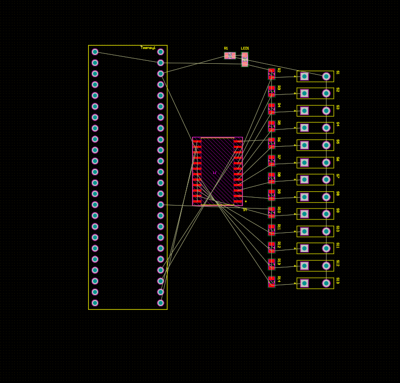
You should now have approximately this:
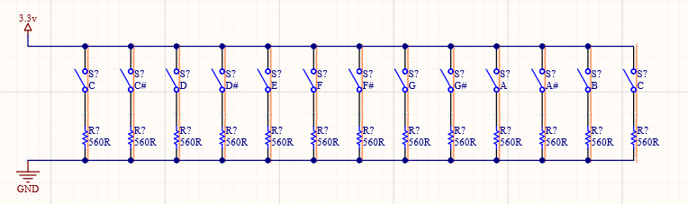
- Now we need to add the switches that we’ll use for our keys. Use the MPS to find “SW-SPST” and place 13 of them.
- Copy and paste the resistor. Change the value to 10k and then paste 12 more. Connect one to each switch.
- Connect the open end of the switches to another 3.3v power port, and connect the open pin of the resistors to a GND port.
Now we should annotate our schematic, meaning, assign every component its own unique designator, which we will need to refer to in our PCB. To do this, press t a a. You will see this dialogue:
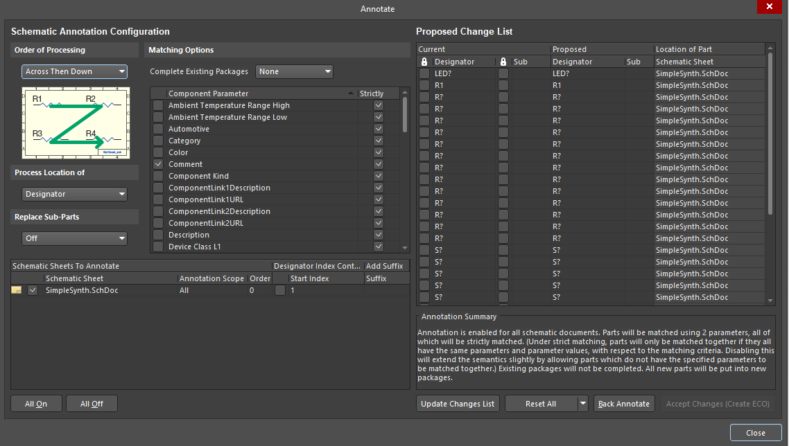
Press "Update Changes List", then press "OK", Press "Accept Changes." When the net dialogue opens, press "Execute Changes." Once finished, you can close those the annotation windows.
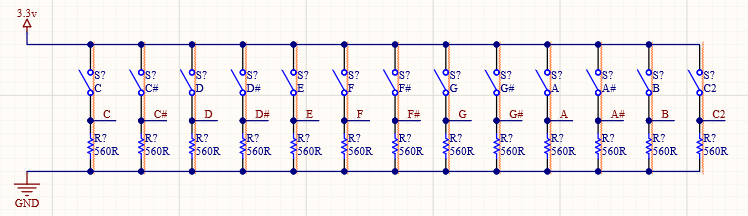
Now we need to create our Nets: the Nets will connect the switches to the Teensy inputs, and we need one per note on our keyboard. Connect wires to the conjunction of the switches and resistors:
and then add the same nets to the Teensy:
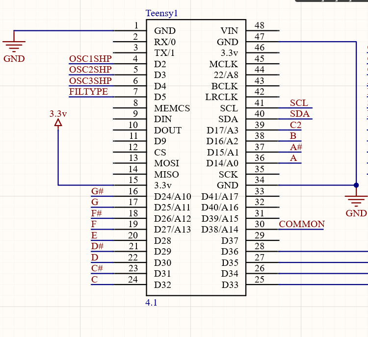
And Now we're done with the schematic ( for now ). This is a very simple schematic; we don't need to add a lot of components because the Teensy handles all of our power conditioning, USB connection, and clocking. All we've really done is enable easy connections between our keys, the multiplexer, and the Teensy. Next we create the PCB layout.
PART 2: PCB Creation
This is the first part of the project where you get to be creative. I won't go into step-by-step detail describing this part of the project once we get the parts into the PCB, but rather talk about some best practices and general considerations. The rest will be up to the user to decide the aesthetics of their board.
While in the schematic document, press d, then u. (For Design, Update PCB Document)
In the pop-up dialogue, validate the changes, then execute the changes. Close the windows.
Now go to the PCB document. If you properly created all your nets and schematic symbols, you should now see all of your components laid out in a row next to a blank slate. It should look something like this:
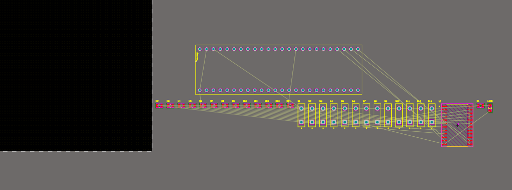
We now need to determine what our PCB will look like. Before we even decide how large our board will be, we need to get a general idea of what our component placement will be. Drag the components into the black area of the page to place them on the PCB area. Keep in mind that the switches should be close to their associated resistors. You also want to place the MUX chip between the switches and the Teensy. Something like this:
Now connect all the nets with wires. I typically use 9mil traces for signals, and 15 - 21mil traces for power connections.
Before we determine our board size, we want to make sure everything will (at least for now) fit. Remember that the audio shield will be on the Teensy, and that it is significantly wider than its parent board. So that we get an idea of its size, I have created an outline for it on the Top Overlay layer, using the line tool. The Audio board is approximately 3.9mm x 3.9mm and isn't seated in the middle of the Teensy, but rather is a bit off center:
Now we know the general size of our board (but keep in mind that we'll be adding more components as we go so leave some space). Create a polygon pour around your components. A simple rectangle is fine. Add the polygon to the GND net.
On layer Mechanical 15, create a box around your polygon pour using the line tool.
While still on layer Mechanical 15, press e, s, y, then d, s, s (Edit, Select, All on Layer, Design, Board Shape, Define Board Shape).
Next we want to create mounting holes for our board. This isn't absolutely necessary, but it's a good habit to get into (trust me). Create a via that is 4mm with a 3mm hole. Copy and paste this so there's one in each corner. We should now have something like this:
Next Steps -------
Adding Controls and Effects
Now we have a board that connects our 13 keys to the Teensy. We still need 12 analog inputs for our controls, though. By using a multiplexer, we will save pins on the Teensy because all 12 pots will be routed into one pin. We are using 4 pins on the Teensy to control the multiplexer, for a total of 5 pins (which is less than 12 = more pins available on the Teensy). Why do we want more pins? Because we want to control aspects of the sound with things like potentiometers (pots). We also want to be able to change oscillator waveforms manually, and therefore need a button or two or three. Now is a good time to decide which effects and controls we want, and the types of physical hardware that will control them.
We're going to have 3 oscillators to generate our waveforms, and we want to cycle through available waveshapes, so we need 3 buttons. We will also want to mix the volumes of the oscillators, so we'll need 3 pots. We're going to have a filter, so we'll need controls for frequency and resolution, and a way to switch between low-pass, high-pass, and band-pass filters. That's two more pots and a button. Then we want to add a delay effect, which typically includes controls for time, feedback, and mix; 3 more pots. Lastly, we will add note envelope controls, or attack, decay, sustain, and release (ADSR) for four more pots. Thus we have a total of 12 pots and 4 buttons. Let's go!
- Back in our SimpleSynth schematic, we need to add potentiometers.
- We don't need a part-specific symbol or footprint, as we just need solder connections for the wires that will connect to the components. Another approach would be to mount these components directly to the board, but that is a slightly more involved process that necessitates a good deal more up-front planning. In order to keep things simple and flexible, we're just going to use wires to connect parts to the board.
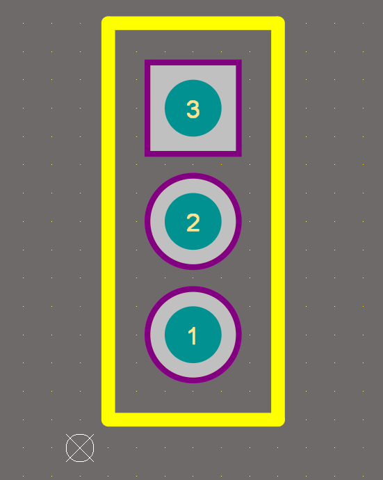
I just made a very basic three-pin symbol and a footprint with standard 4mm x 3mm holes, 2mm spacing.
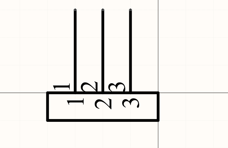
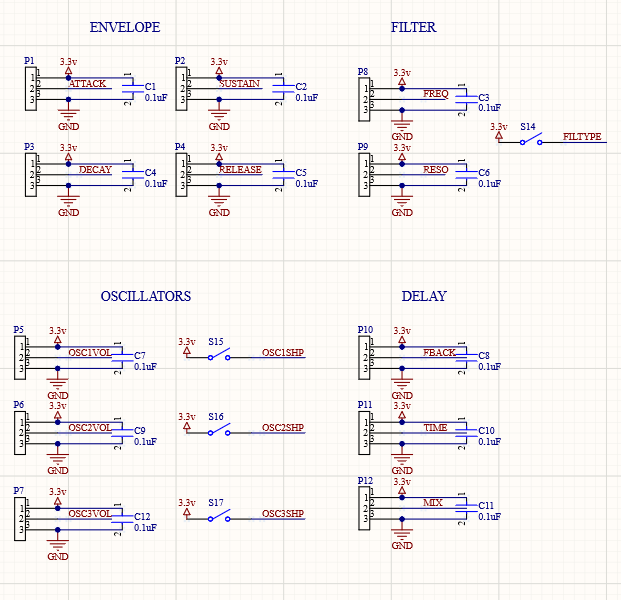
- Once you've made your symbol and footprint, place them in the schematic. I placed mine in such a way that they are grouped together according to their function. Add net labels to denote the component's function.
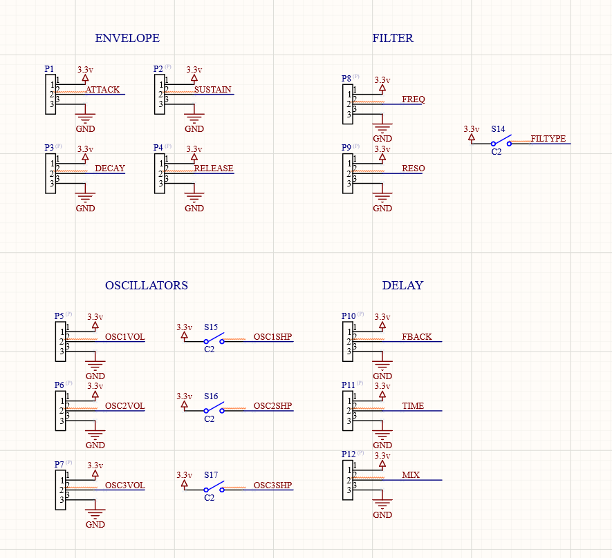
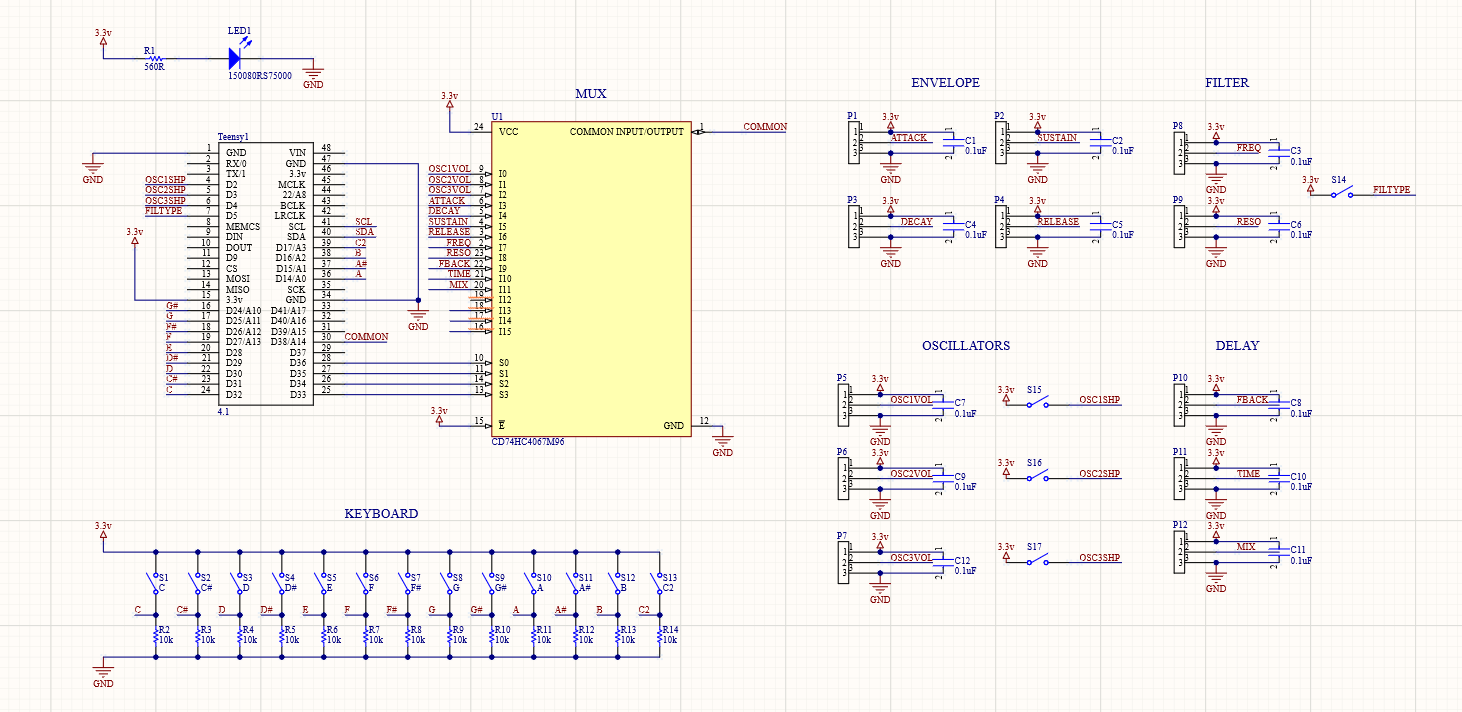
- Once you've placed and labelled your pots and switches, add corresponding net labels to the MUX. Best practice is to group similar functions together where possible. You should now have something akin to this:
Now we need to add our new parts to the PCB. Update the PCB from the schematic as we did before, and place the new components on the board. You will ( most likely ) need to move things around on your existing PCB, and possibly extend it.
As you layout your board, you'll often find yourself making changes that facilitate easier routing. One of the things I did was to reorder the last 5 pins on the MUX so that I wouldn't have to cross too many wires while routing.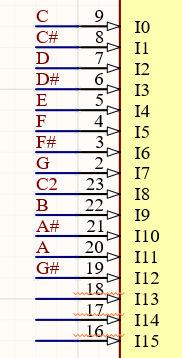
Route all your traces.
Lastly, we're going to add some filtering capacitors to the potentiometers. This will greatly reduce the amount of noise in our circuit and allow for cleaner, more stable readings on our analog inputs. Choose a 0805 capacitor from the Manufacturer Part Search, and change the value to "0.1uF" in its comment.
Copy and paste the capacitor so that there is one connected to the 3.3v pin on every potentiometer. Connect the other leg of the capacitor to GND. Don't forget to annotate the schematic so the caps have numbered designators. Now it should look something like this:
Update your PCB document.
Place all the caps to their associated pots.
Route traces between the caps and pots.
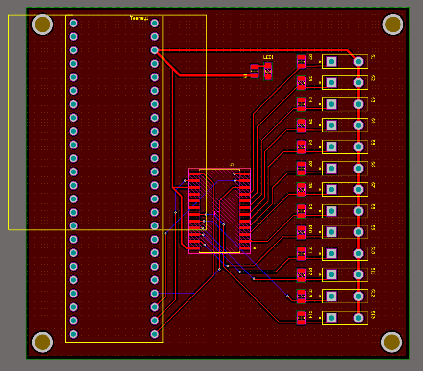
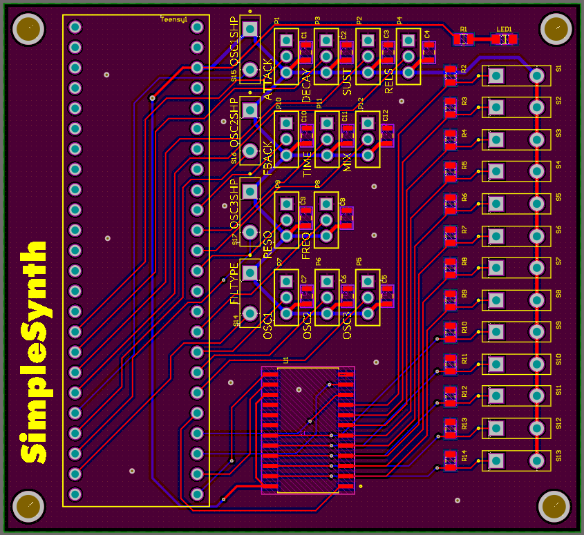
Finishing up: You can now customize your board further by adding text, labels, and things like that. It's a good idea to arrange the component designators so they face the same way and are legible.
And we're done with the circuit board portion of the project! You should now have something that looks like this:
You can now order your boards. For instructions on how to do so, follow these instructions:
Part 3: Designing the Enclosure
We want something practical and sturdy for the SimpleSynth's enclosure. We should consider where things make the most sense in terms of placement, functionality, and form. We're going to start by creating a simple box using makercase.com.
Choose "Basic Box" on the MakerCase homepage.
Enter the dimensions for you box. You can choose whatever makes sense to you, but I chose W=8, H=2, D=5.
Choose your material thickness. I chose 1/4" because I want the case to be sturdy, but yours doesn't need to be that thick.
Choose "Finger" for the edge joints and a finger size that isn't too small or large. I went with .885".
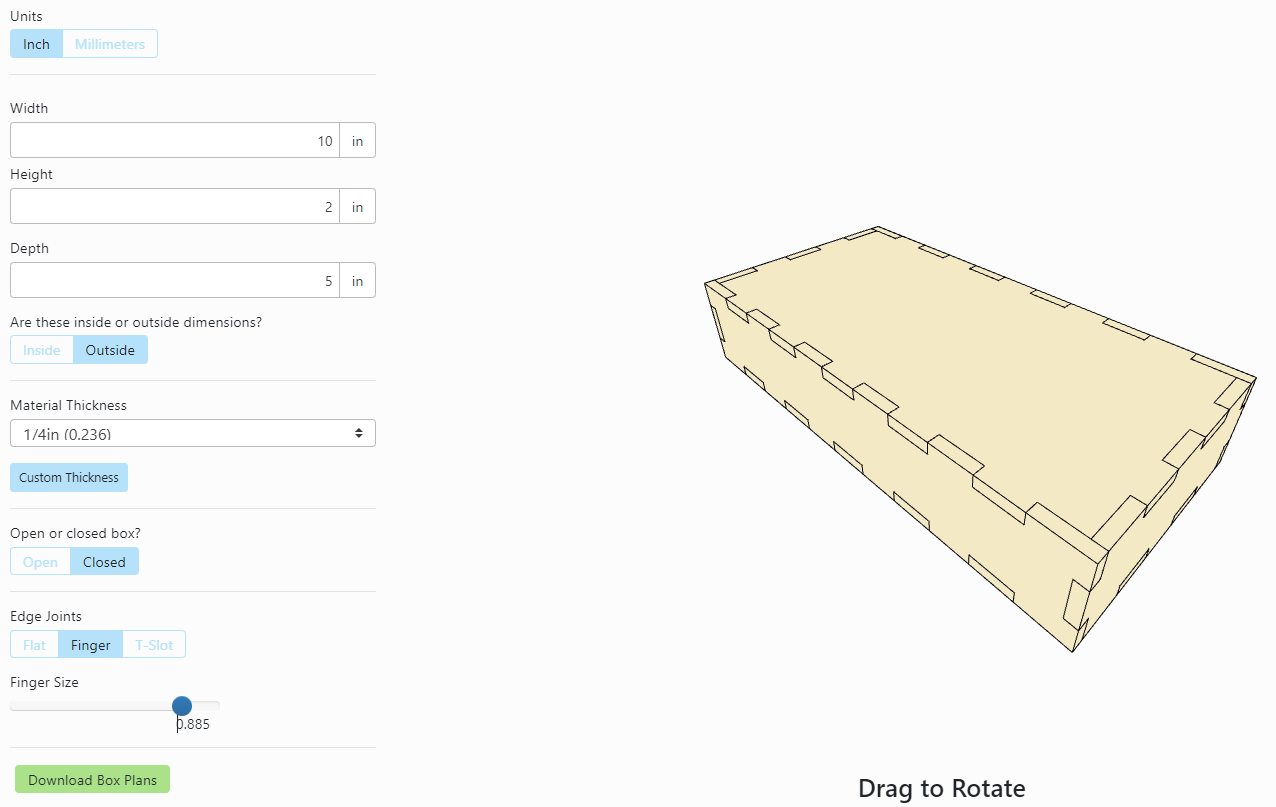
Click "Download Box Plans". Disable panel labels, and click "Download SVG" and save the file.
Now open that file in Adobe Illustrator.
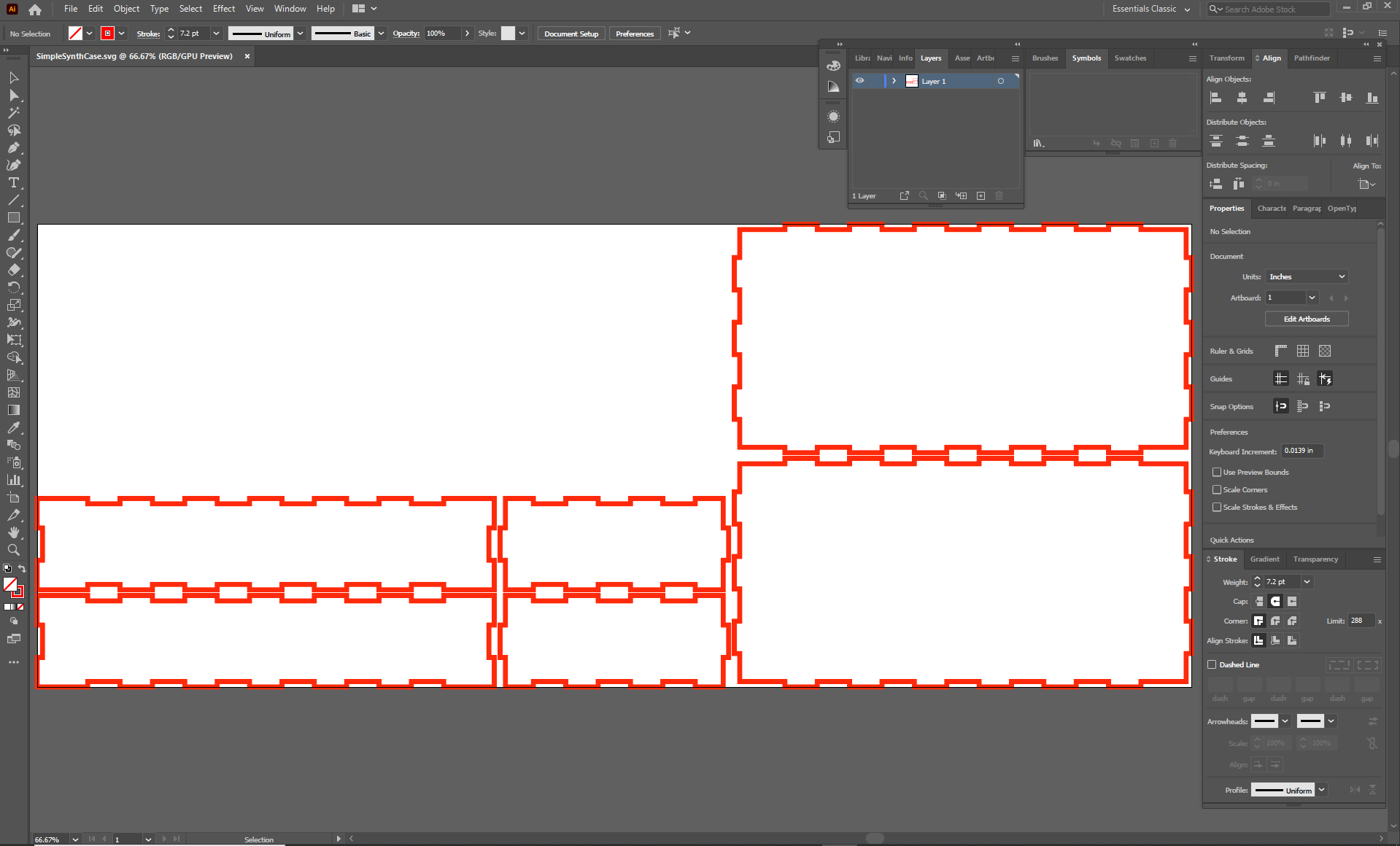
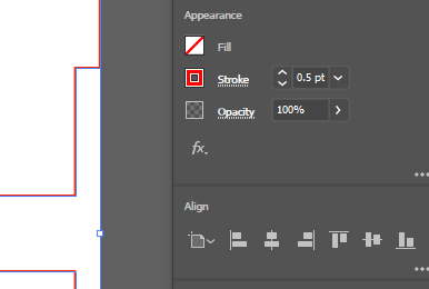
Change the stroke weight for the lines to 0.5.
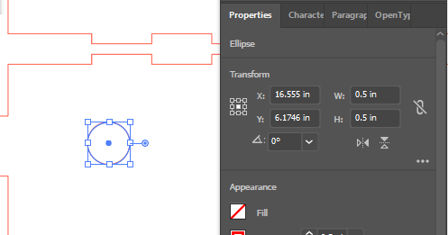
We need to make 12 holes for the potentiometers, so create an ellipse while holding down Shift and Alt (this creates and equilateral ellipse [circle] drawn from the center). Draw it out to approximately .25".
In the Transform section of the Properties window, change the W/H to .25in so they are exact.
Make 11 copies of the hole.
Here it's probably a good idea to lay out a grid. Press CTRL+R to bring up Rulers.
Use the Selection Tool (V) to drag guidelines from the rulers onto the face of your box where you want them. I chose a 1" grid for the controls.
Create another circle that is .5" and make 12 copies. These will be the keyboard keys.
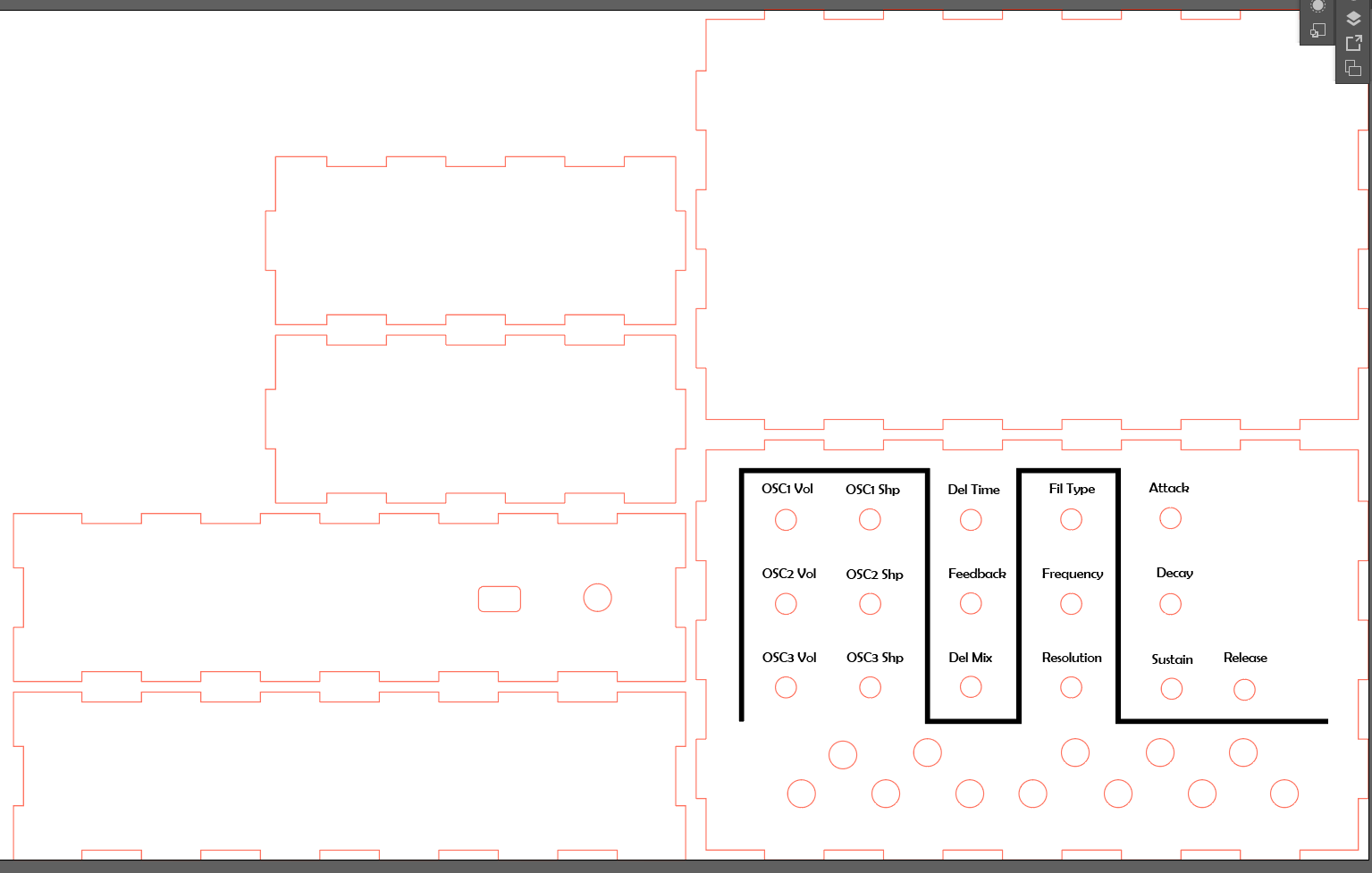
Lay your holes out in a way that makes sense to you. I grouped mine together according to function as so:
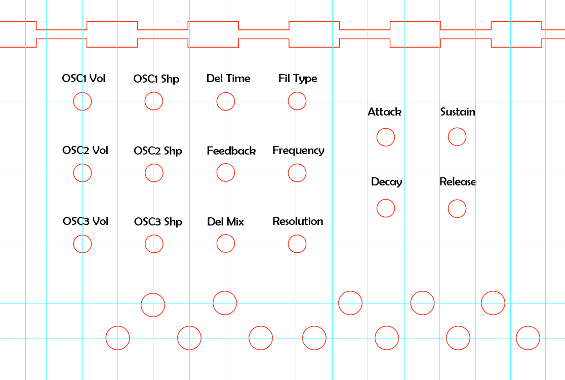
Use the Text Tool (T) to create labels for your controls.
If you find it helpful, you can create lines around your controls to delineate their functional groups.
On one of the other faces ( the short face if you want your plugs on the side, the long face if you want them in back ) paste one of the .5" holes. This is for our audio output.
Next to that hole, create a rounded rectangle that is 5mm x 3mm. This is for our power/USB connector.
Now we're done with the enclosure design, and you should have something in the neighborhood of this:
You can now cut the enclosure out using the laser cutter. Follow the tutorial here for instructions on how to do so.
Part 4: Programming the Synthesizer
The next part of this project will involve coding the functions of our synth. For this we will use the Teensy Audio System Design Tool
We are going to build our synthesizer here, including the oscillators, mixers, delay and filter functions, and audio routing. We will do this by selecting code blocks from the left side of the page and adding them to our design.
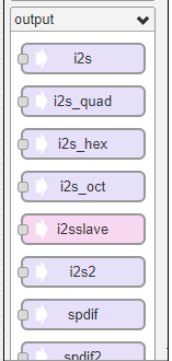
From the output section of the objects menu, select i2s. We need this object in order to establish audio connection between the Teensy and the Audio Board.
Next, go to the synth section of the menu and grab the waveform object.
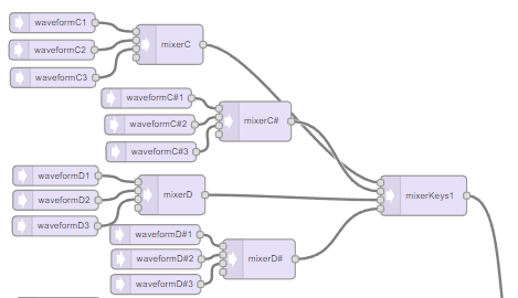
Mono- Vs. Poly-Synths - Synthesizers use oscillators to generate waveforms. An oscillator is only capable of generating one waveform, at one frequency, at a time. Therefore, if we want our synth to be able to play chords, or more than one note at a time, we need multiple oscillators. Since we have a total of 13 notes that can be played, and we want 3 oscillators playing at all times, we need 39 oscillators.Grab 38 more waveform objects and place them in descending order, one below the previous.
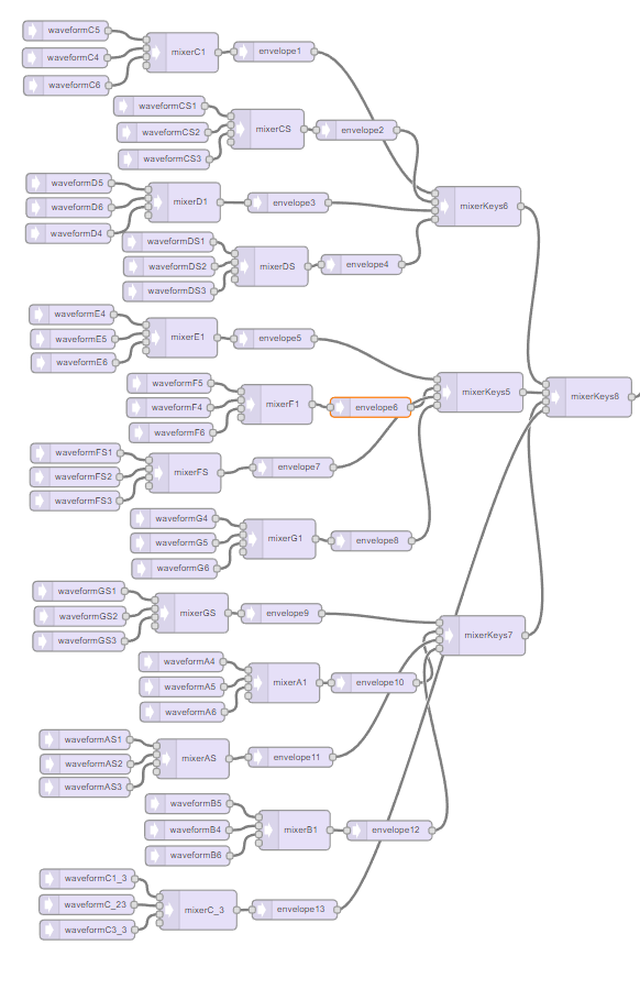
Arrange your waveform objects in groups of three and connect each set of three to a mixer, then to an envelope.
Name your waveform and mixer objects like so:
Once you connect all the objects, grab an i2c object from the left menu and place it on your layout. (We need at least 1 input or output in order to copy our code to Arduino.) You should now have something like this:
Next we'll need an envelope to generate our note shapes.
Add a filter object.
Add a mixer object, name it mixerFilter1, and connect the filter outputs to its inputs.
Now add a delay.
Add two mixers, name them mixerDelay1/2, and connect the delay outputs to their inputs.
Add a final mixer, name it mixerOut. Connect the delayMixer outputs to the mixerOut inputs, then connect the mixerOut outputs to the i2s inputs. You should have something like this:
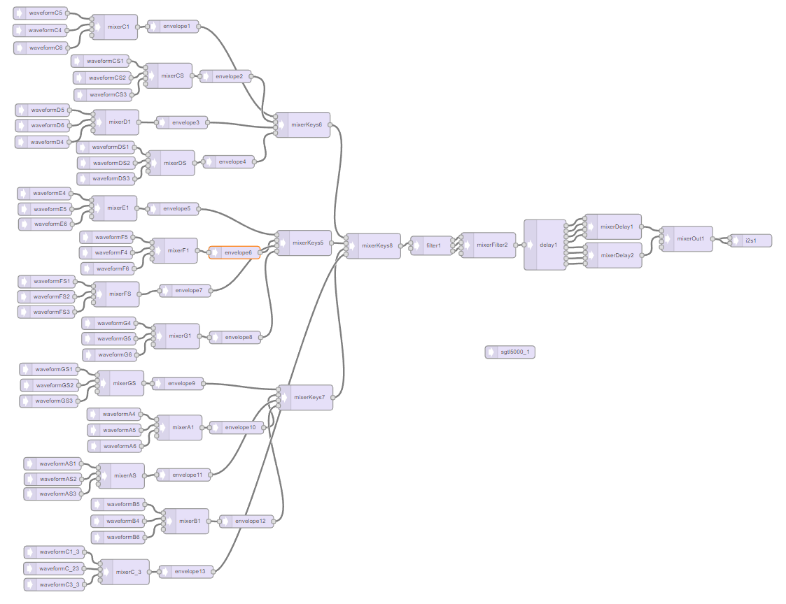
Lastly, from the control section of the menu, add the sgtl5000 object. This establishes the connection between the Teensy and the audio codec via I2S.
You have now created what is essentially synthesizer's functional diagram and signal flow chart. Now we move over to Arduino
Moving To Arduino...
Importing from ASDT
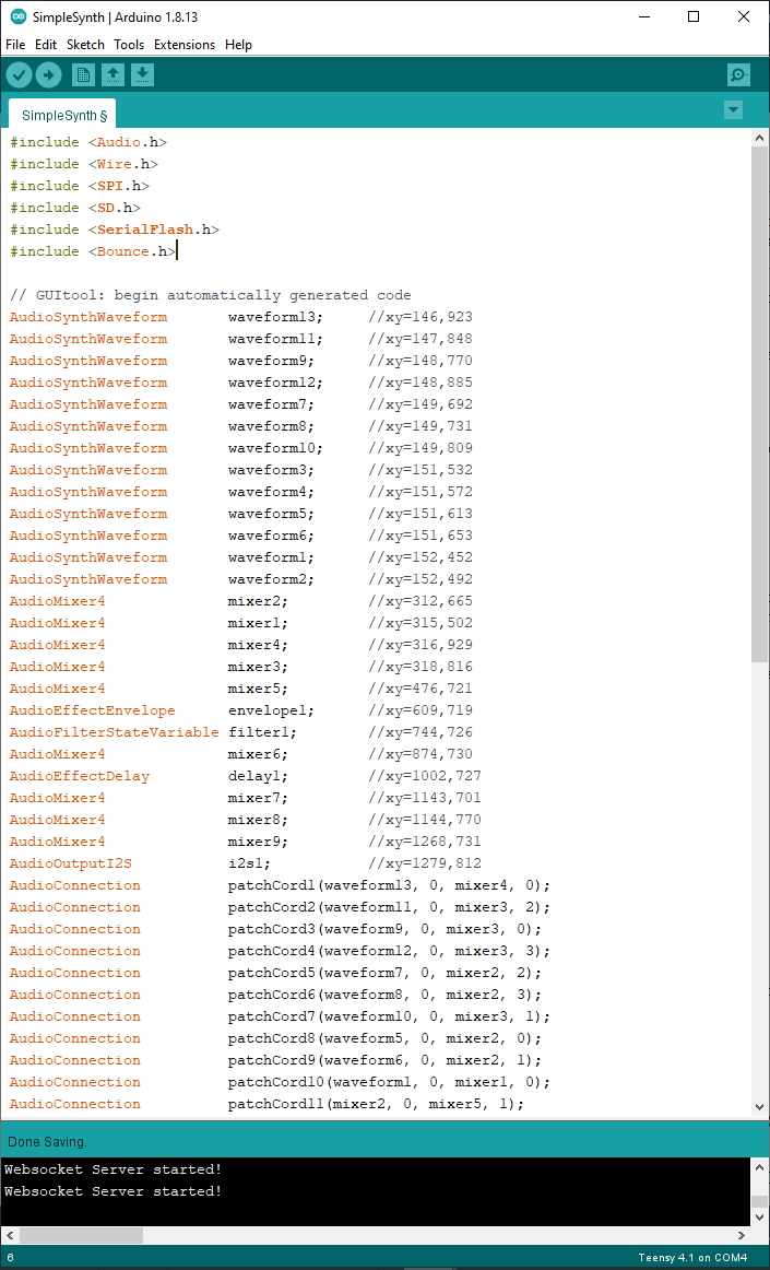
Click the red Export button at the top of the page and copy the code that pops up.
Open Arduino and paste the code above the setup() function in a new window. The Audio System Design Tool has provided us with the necessary headers, classes, and functions for our synth. We also need to include the header Bounce.h
The setup() function...
Now we add the necessary functions to our setup(). Most of the objects we used in the ASDT require some sort of initialization. We'll need to check each object's functions to see how it is initialized and how to call its functions.
One of the really cool and useful things about the Audio System Design Tool is that it very clearly lays out the functions of each object, including all inputs and outputs. When you select an object, its properties are displayed on the right side of the page. There you can also find helpful notes and examples that use that object.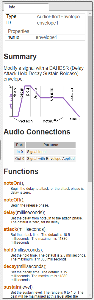
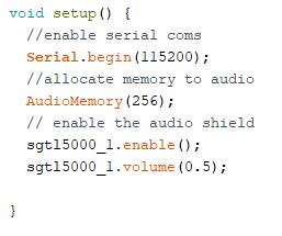
By checking each object's functions in the ASDT, we can find out how to initialize them. Another helpful practice is to check out the example files listed for each object. For the purposes of this project description, I won't delve too far into what every library does, but provide minimal descriptions of why we need it. We'll start by adding and initializing serial communication: Serial.begin(115200);
We also need to allocate sufficient memory to audio processing: AudioMemory(256);
Then we'll enable and initiate our audio codec: sgtl5000_1.enable(); sgtl5000.volume(0.5);
Next, above the setup() function, we'll initialize our control buttons with the Teensy's built-in Button library.
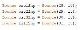
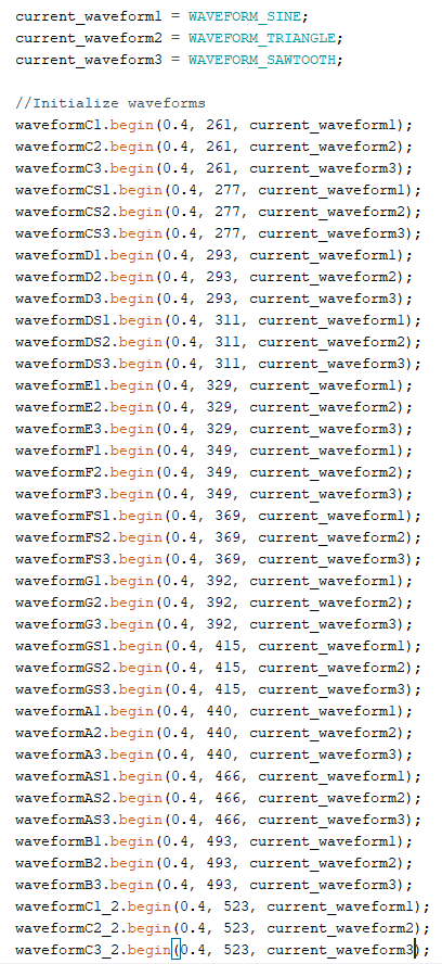
...and initialize our waveform variables:

Now we'll assign waveforms to our current_waveform variables. Then we'll call the waveform.begin() function, which initializes the waveform amplitude, frequency, and shape. We need to initialize all three waveforms for all 13 notes.
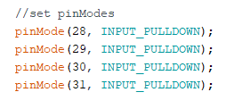
Then set the pinMode for each of our control buttons:
Setting Up the Multiplexer
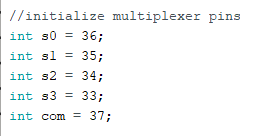
Now to set up the multiplexer. For this we'll need a few things. First, before the setup() function, initialize the pin variables:
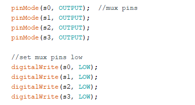
Then, in the setup() function, set the pinModes and set the pins low with the digitalWrite() function :
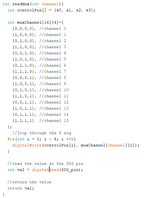
Then we need to create a function that will read from the multiplexer by setting the control pins to loop through its inputs. Place this after the loop function at the bottom of your code.
Moving on to the loop() function