IR Beam Breaker with a Simple WiFi Web Server (ESP32)
By Blake Iwaisako
Description
The IR beam break system can be used for many applications including security and data collecting. Whenever a person or object is detected (when the IR beam is broken) the instance will be logged on the ESP32 alongside the time the instance took place. The ESP32 will also be capable of sending you emails whenever a beam break occurs or after a certain period of time. By connecting to the server via IP address, a second party can see the full log of instances recorded. In this project, we will learn how to use IR beam break sensors, create a webserver using the ESP32, attain the current time from an NTP server, and send email notifications using SMTP.
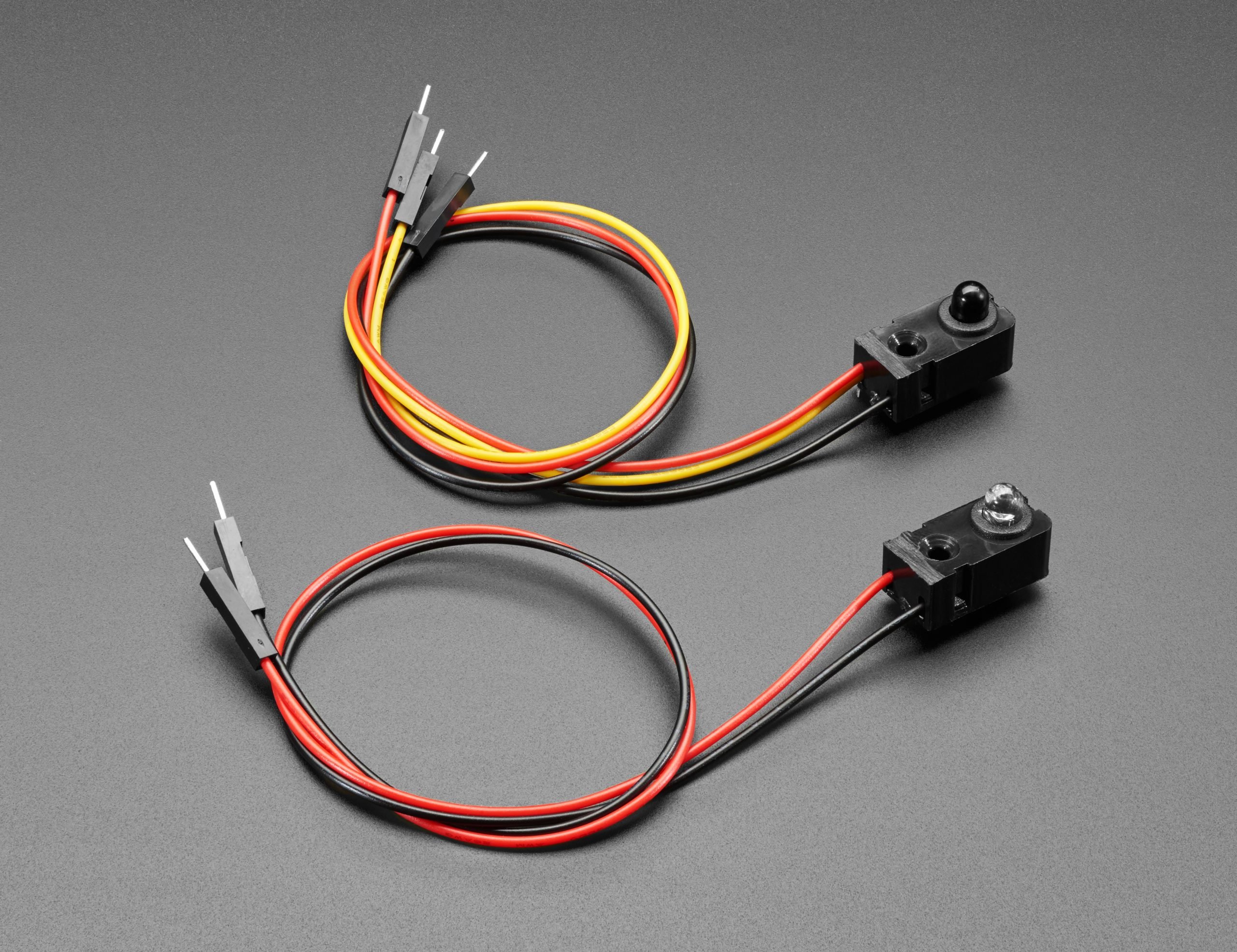
IR Beam Break Sensors
An infrared beam break sensor has a very simple transmitter/receiver design. The transmitter is an infrared light that is invisible to the human eye making it ideal for low-profile security systems. The receiver detects infrared light and will output a signal if it is detected.
These are Adafruit IR Beam Break Sensors that I will be using for this project.
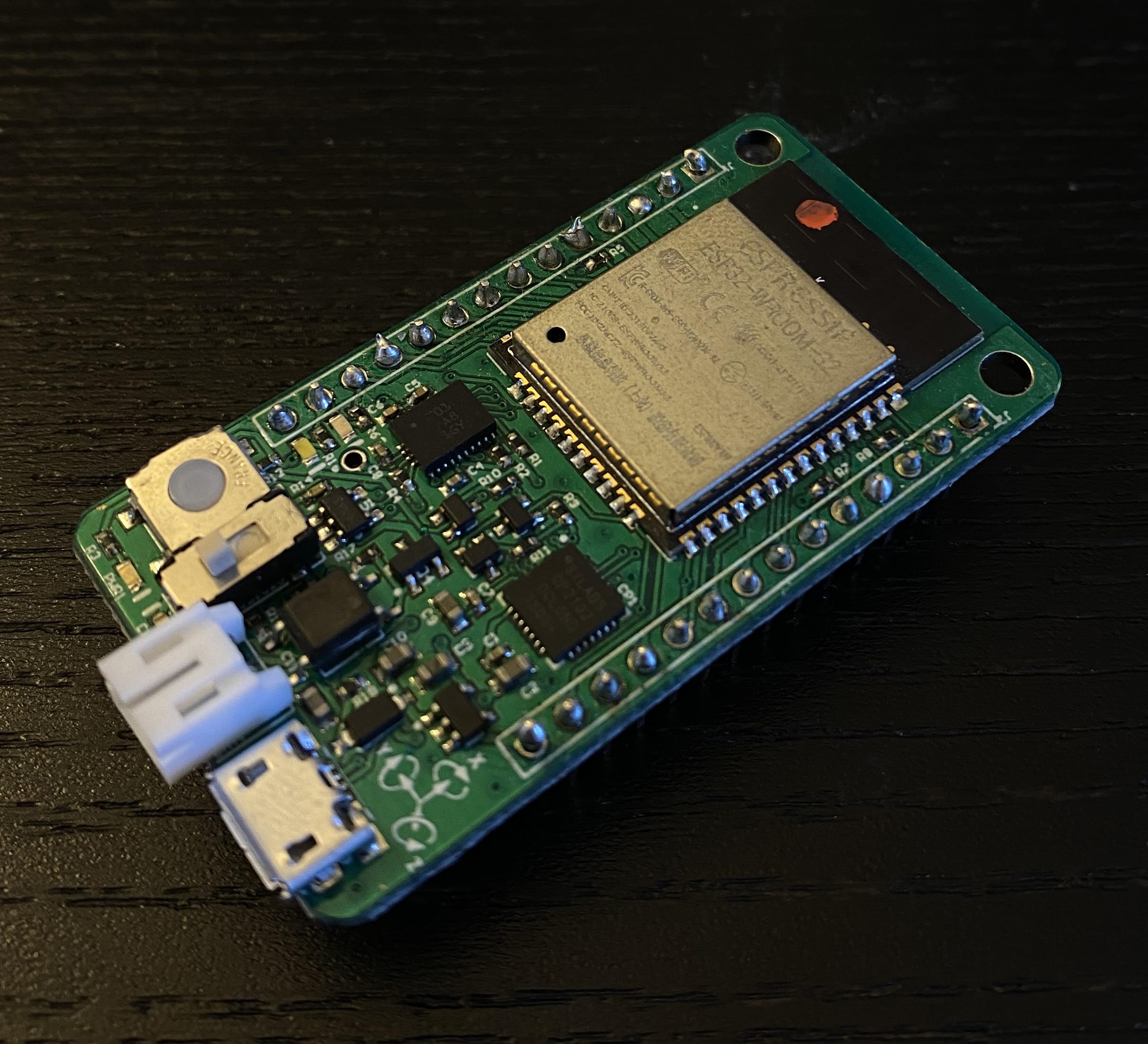
For this project, I will be using an ESP32 microcontroller. The ESP32 is an amazing module that comes with integrated WiFi capabilities and can be programmed using the Arduino IDE.
For this demonstration we will be using the ESP32 Wrover Module shown here:
Installing the ESP32 Library on Arduino IDE
Follow this step-by-step guide to install the ESP32 library. You only need to install the library as the rest of the tutorial goes about testing the ESP32's WiFi capabilities, however, feel free to try this out. Just make sure you select the correct board from the "Board" menu.
Here is the link to the library that you paste into the "Additional Board Manager URLs" field.
https://raw.githubusercontent.com/espressif/arduino-esp32/gh-pages/package_esp32_index.json
WiFi Web Server
A WiFi web server on the ESP32 creates an IP address allowing you to access the board's client from a browser connected to the same network.
Go through the entirety of this tutorial to understand how to create a WiFi server on the ESP32 and edit a webpage using HTML. The tutorial shows you how to control GPIO pins 26 and 27 via a web server that can be accessed using an IP address.
I have created an edited version of the code to control a servo motor using a library by Kevin Harrington called ESP32Servo.h. It will be important to learn how the code works so become familiar with the WiFi Client coding procedure.
/*********
  Rui Santos
  Complete project details at http://randomnerdtutorials.com
*********/
// Edited By Blake Iwaisako to control a Servo motor
// Include ESP32 Servo Library by Kevin Harrington
// Load Wi-Fi library

#include <WiFi.h>
#include <ESP32Servo.h>

// Replace with your network credentials
const char* ssid = "replace with your ssid";
const char* password = "replace with your password";

// Set web server port number to 80
WiFiServer server(80);
Servo myservo;

// Variable to store the HTTP request
String header;

// Auxiliar variables to store the current output state
String output26State = "off";
String output27State = "off";


// Assign output variables to GPIO pins
const int output26 = 26;
const int output27 = 27;

// Current time
unsigned long currentTime = millis();
// Previous time
unsigned long previousTime = 0;
// Define timeout time in milliseconds (example: 2000ms = 2s)
const long timeoutTime = 2000;

void setup() {
  Serial.begin(115200);
  // Initialize the output variables as outputs
  myservo.attach(26);
  myservo.write(130);
  pinMode(output27, OUTPUT);
  // Set outputs to LOW
  digitalWrite(output26, LOW);
  digitalWrite(output27, LOW);

  // Connect to Wi-Fi network with SSID and password
  Serial.print("Connecting to ");
  Serial.println(ssid);
  WiFi.begin(ssid, password);
  while (WiFi.status() != WL_CONNECTED) {
    delay(500);
    Serial.print(".");
  }
  // Print local IP address and start web server
  Serial.println("");
  Serial.println("WiFi connected.");
  Serial.println("IP address: ");
  Serial.println(WiFi.localIP());
  server.begin();
}

void loop() {
  WiFiClient client = server.available();   // Listen for incoming clients

  if (client) {                             // If a new client connects,
    currentTime = millis();
    previousTime = currentTime;
    Serial.println("New Client.");          // print a message out in the serial port
    String currentLine = "";                // make a String to hold incoming data from the client
    while (client.connected() && currentTime - previousTime <= timeoutTime) {  // loop while the client's connected
      currentTime = millis();
      if (client.available()) {             // if there's bytes to read from the client,
        char c = client.read();             // read a byte, then
        Serial.write(c);                    // print it out the serial monitor
        header += c;
        if (c == '\n') {                    // if the byte is a newline character
          // if the current line is blank, you got two newline characters in a row.
          // that's the end of the client HTTP request, so send a response:
          if (currentLine.length() == 0) {
            // HTTP headers always start with a response code (e.g. HTTP/1.1 200 OK)
            // and a content-type so the client knows what's coming, then a blank line:
            client.println("HTTP/1.1 200 OK");
            client.println("Content-type:text/html");
            client.println("Connection: close");
            client.println();

            // turns the GPIOs on and off
            if (header.indexOf("GET /26/on") >= 0) {
              Serial.println("GPIO 26 on");
              output26State = "closed";
              myservo.write(60);
            } else if (header.indexOf("GET /26/off") >= 0) {
              Serial.println("GPIO 26 off");
              output26State = "open";
              myservo.write(130);
            } else if (header.indexOf("GET /27/on") >= 0) {
              Serial.println("GPIO 27 on");
              output27State = "on";
              digitalWrite(output27, HIGH);
            } else if (header.indexOf("GET /27/off") >= 0) {
              Serial.println("GPIO 27 off");
              output27State = "off";
              digitalWrite(output27, LOW);
            }

            // Display the HTML web page
            client.println("<!DOCTYPE html><html>");
            client.println("<head><meta name=\"viewport\" content=\"width=device-width, initial-scale=1\">");
            client.println("<link rel=\"icon\" href=\"data:,\">");
            // CSS to style the on/off buttons
            // Feel free to change the background-color and font-size attributes to fit your preferences
            client.println("<style>html { font-family: Helvetica; display: inline-block; margin: 0px auto; text-align: center;}");
            client.println(".button { background-color: #4CAF50; border: none; color: white; padding: 16px 40px;");
            client.println("text-decoration: none; font-size: 30px; margin: 2px; cursor: pointer;}");
            client.println(".button2 {background-color: #416664;}</style></head>");

            // Web Page Heading
            client.println("<body><h1>GPIO 26 & 27</h1>");

            // Display current state, and ON/OFF buttons for GPIO 26
            client.println("<p>GPIO 26 - State " + output26State + "</p>");
            // If the output26State is off, it displays the ON button
            if (output26State == "open") {
              client.println("<p><a href=\"/26/on\"><button class=\"button\">Close</button></a></p>");
            } else {
              client.println("<p><a href=\"/26/off\"><button class=\"button button2\">Open</button></a></p>");
            }

            // Display current state, and ON/OFF buttons for GPIO 27
            client.println("<p>GPIO 27 - State " + output27State + "</p>");
            // If the output27State is off, it displays the ON button
            if (output27State == "off") {
              client.println("<p><a href=\"/27/on\"><button class=\"button\">ON</button></a></p>");
            } else {
              client.println("<p><a href=\"/27/off\"><button class=\"button button2\">OFF</button></a></p>");
            }
            client.println("</body></html>");

            // The HTTP response ends with another blank line
            client.println();
            // Break out of the while loop
            break;
          } else { // if you got a newline, then clear currentLine
            currentLine = "";
          }
        } else if (c != '\r') {  // if you got anything else but a carriage return character,
          currentLine += c;      // add it to the end of the currentLine
        }
      }
    }
    // Clear the header variable
    header = "";
    // Close the connection
    client.stop();
    Serial.println("Client disconnected.");
    Serial.println("");
  }
}
IR Beam Break
Full tutorial here.
This code is bare bones but you can use it to understand how the IR beam break sensor works and how you can integrate parts of it with the WiFi web server. This code simply shows whether or not the IR beam is broken and when it does break a connected LED will blink.
// from Adafruit edited by Blake Iwaisako

#define LEDPIN 27
#define SENSORPIN 14

int sensorState = 0;
int lastState = 0;

void setup() {
  pinMode(LEDPIN, OUTPUT);
  pinMode(SENSORPIN, INPUT);
  digitalWrite(SENSORPIN, HIGH);
  Serial.begin(115200);

}

void loop() {
  sensorState = digitalRead(SENSORPIN);
  if (sensorState && !lastState){
    Serial.print("Unbroken");
  }

  if (!sensorState && lastState) {
    Serial.print("Broken");
    digitalWrite(LEDPIN, HIGH);
    delay(100);
    digitalWrite(LEDPIN, LOW);
  }
  lastState = sensorState;
}
NTP Server
Full tutorial here
Network Time Protocol is used to sync your computers to the current time using the internet. An ESP32 with WiFi capabilities can access this and attain the current time. To do this you will NEED to download and install a separate library called NTPClient.h which can be found in the full tutorial.
This code will simply update the current time every second and display in the serial monitor.
Below I have pasted a slightly edited version of the code found on the full tutorial:
/*********
  Rui Santos
  Complete project details at https://randomnerdtutorials.com
  Based on the NTP Client library example
*********/

#include <WiFi.h>
#include <NTPClient.h>
#include <WiFiUdp.h>

// Replace with your network credentials
const char* ssid     = "REPLACE_WITH_YOUR_SSID";
const char* password = "REPLACE_WITH_YOUR_PASSWORD";

// Define NTP Client to get time
WiFiUDP ntpUDP;
NTPClient timeClient(ntpUDP);

// Variables to save date and time
String formattedDate;
String dayStamp;
String timeStamp;

void setup() {
  // Initialize Serial Monitor
  Serial.begin(115200);
  Serial.print("Connecting to ");
  Serial.println(ssid);
  WiFi.begin(ssid, password);
  while (WiFi.status() != WL_CONNECTED) {
    delay(500);
    Serial.print(".");
  }
  // Print local IP address and start web server
  Serial.println("");
  Serial.println("WiFi connected.");
  Serial.println("IP address: ");
  Serial.println(WiFi.localIP());

// Initialize a NTPClient to get time
  timeClient.begin();
  // Set offset time in seconds to adjust for your timezone, for example:
  // GMT +1 = 3600
  // GMT +8 = 28800
  // GMT -1 = -3600
  // GMT 0 = 0
  timeClient.setTimeOffset(-25200);   // PST -7 = -252000
}
void loop() {
  while(!timeClient.update()) {
    timeClient.forceUpdate();
  }
  // The formattedDate comes with the following format:
  // 2018-05-28T16:00:13Z
  // We need to extract date and time
  formattedDate = timeClient.getFormattedDate();
  Serial.println(formattedDate);

  // Extract date
  int splitT = formattedDate.indexOf("T");
  dayStamp = formattedDate.substring(0, splitT);
  Serial.print("DATE: ");
  Serial.println(dayStamp);
  // Extract time
  timeStamp = formattedDate.substring(splitT+1, formattedDate.length()-1);
  Serial.print("HOUR: ");
  Serial.println(timeStamp);
  delay(1000);
}
Optional: Sending Email Notifications (SMTP)
Full tutorial here
Simple Mail Transfer Protocol is used by mail servers such as GMail, Outlook, Yahoo, etc. to send and receive emails. The ESP32 can login to your mail account and send emails written in the Arduino IDE using HTML formatting. The tutorial focuses on Gmail specifically and offers a workaround in case you are using 2-factor authentication.
Once again here is the code with a few changes for our purposes:
/*
  Rui Santos
  Complete project details at:
   - ESP32: https://RandomNerdTutorials.com/esp32-send-email-smtp-server-arduino-ide/
   - ESP8266: https://RandomNerdTutorials.com/esp8266-nodemcu-send-email-smtp-server-arduino/

  Permission is hereby granted, free of charge, to any person obtaining a copy of this software and associated documentation files.
  The above copyright notice and this permission notice shall be included in all copies or substantial portions of the Software.
  Example adapted from: https://github.com/mobizt/ESP-Mail-Client
*/

// To send Emails using Gmail on port 465 (SSL), you need to create an app password: https://support.google.com/accounts/answer/185833

#include <Arduino.h>
#if defined(ESP32)
  #include <WiFi.h>
#endif
#include <ESP_Mail_Client.h>

#define WIFI_SSID "REPLACE_WITH_YOUR_SSID"
#define WIFI_PASSWORD "REPLACE_WITH_YOUR_PASSWORD"

#define SMTP_HOST "smtp.gmail.com"
#define SMTP_PORT 465

/* The sign in credentials */
#define AUTHOR_EMAIL "YOUR_EMAIL@XXXX.com"
#define AUTHOR_PASSWORD "YOUR_EMAIL_PASS"  // If using 2-factor copy and paste unique code for the ESP32

/* Recipient's email*/
#define RECIPIENT_EMAIL "RECIPIENTE_EMAIL@XXXX.com"

/* The SMTP Session object used for Email sending */
SMTPSession smtp;

/* Callback function to get the Email sending status */
void smtpCallback(SMTP_Status status);

void setup(){
  Serial.begin(115200);
  Serial.println();
  Serial.print("Connecting to AP");
  WiFi.begin(WIFI_SSID, WIFI_PASSWORD);
  while (WiFi.status() != WL_CONNECTED){
    Serial.print(".");
    delay(200);
  }
  Serial.println("");
  Serial.println("WiFi connected.");
  Serial.println("IP address: ");
  Serial.println(WiFi.localIP());
  Serial.println();

  /** Enable the debug via Serial port
   * none debug or 0
   * basic debug or 1
  */
  smtp.debug(1);

  /* Set the callback function to get the sending results */
  smtp.callback(smtpCallback);

  /* Declare the session config data */
  ESP_Mail_Session session;

  /* Set the session config */
  session.server.host_name = SMTP_HOST;
  session.server.port = SMTP_PORT;
  session.login.email = AUTHOR_EMAIL;
  session.login.password = AUTHOR_PASSWORD;
  session.login.user_domain = "";

  /* Declare the message class */
  SMTP_Message message;

  /* Set the message headers */
  message.sender.name = "ESP";
  message.sender.email = AUTHOR_EMAIL;
  message.subject = "ESP Test Email";
  message.addRecipient("Sara", RECIPIENT_EMAIL);

  /*Send HTML message*/
  String htmlMsg = "<div style=\"color:#2f4468;\"><h1>Hello World!</h1><p>- Sent from ESP board</p></div>";
  message.html.content = htmlMsg.c_str();
  message.html.content = htmlMsg.c_str();
  message.text.charSet = "us-ascii";
  message.html.transfer_encoding = Content_Transfer_Encoding::enc_7bit;

  /*
  //Send raw text message
  String textMsg = "Hello World! - Sent from ESP board";
  message.text.content = textMsg.c_str();
  message.text.charSet = "us-ascii";
  message.text.transfer_encoding = Content_Transfer_Encoding::enc_7bit;

  message.priority = esp_mail_smtp_priority::esp_mail_smtp_priority_low;
  message.response.notify = esp_mail_smtp_notify_success | esp_mail_smtp_notify_failure | esp_mail_smtp_notify_delay;*/

  /* Set the custom message header */
  //message.addHeader("Message-ID: <abcde.fghij@gmail.com>");

  /* Connect to server with the session config */
  if (!smtp.connect(&session))
    return;

  /* Start sending Email and close the session */
  if (!MailClient.sendMail(&smtp, &message))
    Serial.println("Error sending Email, " + smtp.errorReason());
}

void loop(){

}

/* Callback function to get the Email sending status */
void smtpCallback(SMTP_Status status){
  /* Print the current status */
  Serial.println(status.info());

  /* Print the sending result */
  if (status.success()){
    Serial.println("----------------");
    ESP_MAIL_PRINTF("Message sent success: %d\n", status.completedCount());
    ESP_MAIL_PRINTF("Message sent failled: %d\n", status.failedCount());
    Serial.println("----------------\n");
    struct tm dt;

    for (size_t i = 0; i < smtp.sendingResult.size(); i++){
      /* Get the result item */
      SMTP_Result result = smtp.sendingResult.getItem(i);
      time_t ts = (time_t)result.timestamp;
      localtime_r(&ts, &dt);

      ESP_MAIL_PRINTF("Message No: %d\n", i + 1);
      ESP_MAIL_PRINTF("Status: %s\n", result.completed ? "success" : "failed");
      ESP_MAIL_PRINTF("Date/Time: %d/%d/%d %d:%d:%d\n", dt.tm_year + 1900, dt.tm_mon + 1, dt.tm_mday, dt.tm_hour, dt.tm_min, dt.tm_sec);
      ESP_MAIL_PRINTF("Recipient: %s\n", result.recipients);
      ESP_MAIL_PRINTF("Subject: %s\n", result.subject);
    }
    Serial.println("----------------\n");
  }
}
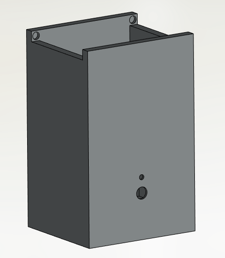
CAD and Building the Device
Both the transmitter and receiver do not need very complicated encasements here are just a few examples of boxes that have holes and holders for the sensors.
IR Transmitter: this can be smaller than the receiver since it does not need to house the ESP32 and extra wiring.
![]()
IR Receiver: This case has to house the ESP32, piezo buzzer, wiring, and IR Receiver.
Optional: create a hole to hold a switch to turn the device on.
Optional: Setup Static IP Address
Prior to this step, every time you wanted to connect to the ESP32 web server you had to check the Serial Monitor for the automatically generated IP Address that changes depending on your connection. However, this can be overridden so that you do not have to check the serial monitor and would rather always use one IP address to access the ESP32.
You do this by using the IPAddress function in Arduino. The values below are from my computer and may be different for your connection. You will at least need to change the local_IP, gateway, and subnet values for your router. To do this go to the command prompt and type in "ipconfig" to bring up your connection's settings that you will just plug in here. These definitions can be placed anywhere before the setup() function in your sketch.
// Necessary
IPAddress local_IP(192, 168, 0, 124);
IPAddress gateway(192, 168, 0, 1);
IPAddress subnet(255, 255, 0, 0);

// Optional
IPAddress primaryDNS(8, 8, 8, 8);
IPAddress secondaryDNS(8, 8, 4, 4);
In the setup() function place this if statement which simply ensures the WiFi was configured correctly and forced to use the IP address you want.
// Configures static IP address
  if (!WiFi.config(local_IP, gateway, subnet, primaryDNS, secondaryDNS)) {
    Serial.println("STA Failed to configure");
  }
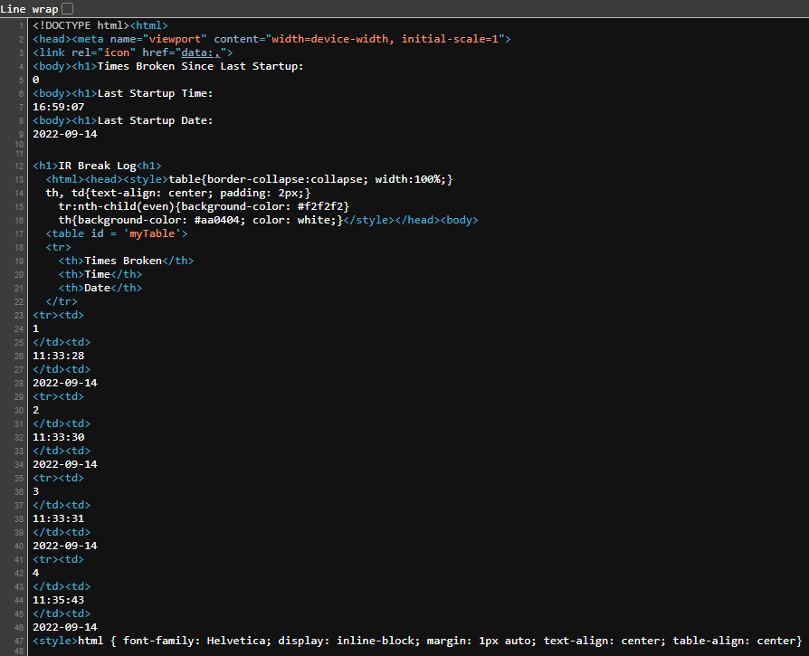
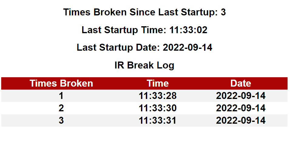
Creating a table in HTML and uploading using SPIFFS
For the last part of this project we will need to create a data log that will be updated every time the IR beam is broken. This table will display the counter, time broken, and date broken values. This may be one of the trickier parts of the whole project as it requires a good deal of debugging and HTML programming within the Arduino IDE.
Tables in HTML
HTML can be used within the Arduino IDE by using the client.print() function. In order to print to the ESP32 web page we need to print HTML code on the client using this function in the main void loop() of the Arduino code. Use the examples below to get a grasp of how to format HTML code.
What are SPIFFS??
SPIFFS stands for Serial Peripheral Interface Flash File System. Essentially this system can store and create simple files directly on the microcontroller by using an onboard flash chip. Files such as .txt can be easily uploaded using the Arduino IDE and edited onboard. This allows us to write in direct HTML language on a .txt file and upload it to the web page client. It also allows us to concatenate our code into easy to edit .txt files.
Why do we need to use SPIFFS when we can just client.print() everything?
The main reason we need to use SPIFFS is because we need to create a dynamic log of our data so that every time the IR beam is broken, a new row of data is added to our table and stays there permanently. This cannot be done easily using just client.print(). It will be much easier to start with HTML code in a .txt file that generates a table and then write code to put another row of data into the file.
Using SPIFFS with an Arduino Plug-in
Link to github and installation instructions
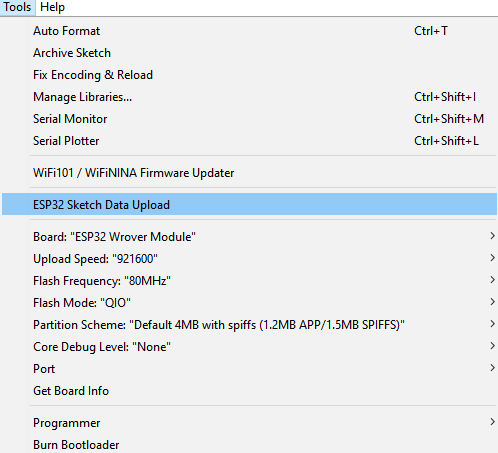
This plug-in allows you to create a "data" folder in your sketch's folder and store .txt files which can be uploaded to the ESP32 through the IDE. After successfully installing the SPIFFS plug in you can look in the "Tools" tab at the top of the screen and notice you have a new tool: "ESP32 Sketch Data Upload".
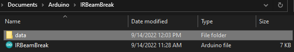
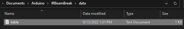
Now that you have installed the plug-in, head to the sketch folder and create another folder named "data". This is where you will store the code for the table.
You can use any HTML code editor to make and export your code to a .txt file. Here I just typed my code into Notepad:
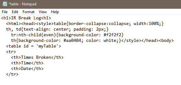
Now when you go back to the Arduino IDE and use the "ESP32 Sketch Data Upload" tool, the plug-in will upload the contents of the data folder into the ESP32. File "table" will be accessible at any time.
Appending content in a file
To dynamically add rows of data to the log we will need to open the table file for appending using FILE_APPEND. Since the table file will always be on display on the webpage, appending the file whenever the IR beam is broken is all that we have to do.
Appending the file to add another row of data should look something like this:
    // Append table file so that it shows another row of log data
    File table = SPIFFS.open("/table.txt", FILE_APPEND);
    table.println("<tr><td>");
    table.println(counter);
    table.println("</td><td>");
    table.println(timeStamp);
    table.println("</td><td>");
    table.println(dayStamp);
    table.close();
Putting it All Together
Now using everything learned from the tutorials above, write code that detects every time the IR beam breaks, logs the break along with the time of the event, and optionally sends an email notification when the break occurs. The log must be accessible via an IP address at least.
Here is a screenshot of my source code. Your code does not need to look like mine at all but feel free to use it as a guide for your project.