LED Audio Sound Level Display VU Meter Analyzer
Overview/Description
For this project you will be building an LED Audio Sound Level Display VU Meter Analyzer or for short a VU-Meter. This device will react to audio intensity and will light up accordingly in an LED bar graph. This exampled involves an ESP-32 S3 and requires you to design a practical PCB for this purpose.
You'll need the following components:
- ESP32S3MINI1 (I'll be referring to is as ESP32 for short)
- Max9814 Microphone
- A few capacitors
- A few resistors
- Two tactile switches of your choosing
- A USB receptacle of your choosing
- A linear voltage regulator of your choosing
- A 2 pin terminal block of your choosing
- 2 diodes of your choosing
Process
This project will challenge your PCB design, soldering, programming, and 3D modeling skills with an emphasis on PCB design.
The process if broken down in the following order.
PCB Design
The first step will be designing an appropriate PCB. You may decide your own layout or construct one similar to mine. This process involves creating or editing symbols and footprints, putting together a layout and designing the PCB. I designed my PCB with KiCad, so this tutorial assumes that you'll do the same but you're more than welcome to use your preferred PCB editor.
Before you start your schematic, I recommend you figure out exactly what components you want to use and if those components are available for sale. I personally order all my components on DigiKey. I'd then recommend that you check if KiCad has a symbol and footprint for such components. You'll most likely find that you'll have to create your own symbol and footprint or copy one of the existing ones in the KiCad libraries from a similar component. You'll have to create a symbol and footprint for the ESP32. Below is an example of a symbol and a footprint that I created for the ESP32.


Once you have symbols and footprints for all your components, including the ESP32, you should begin your schematic layout. Feel free to use mine as reference but by no means does it have to look the same. Make sure your LEDs are connected properly as well as your switches and voltage regulator. Below is my schematic for reference.
Notice how the diodes are placed in order to ensure current strictly flows into the linear voltage regulator.

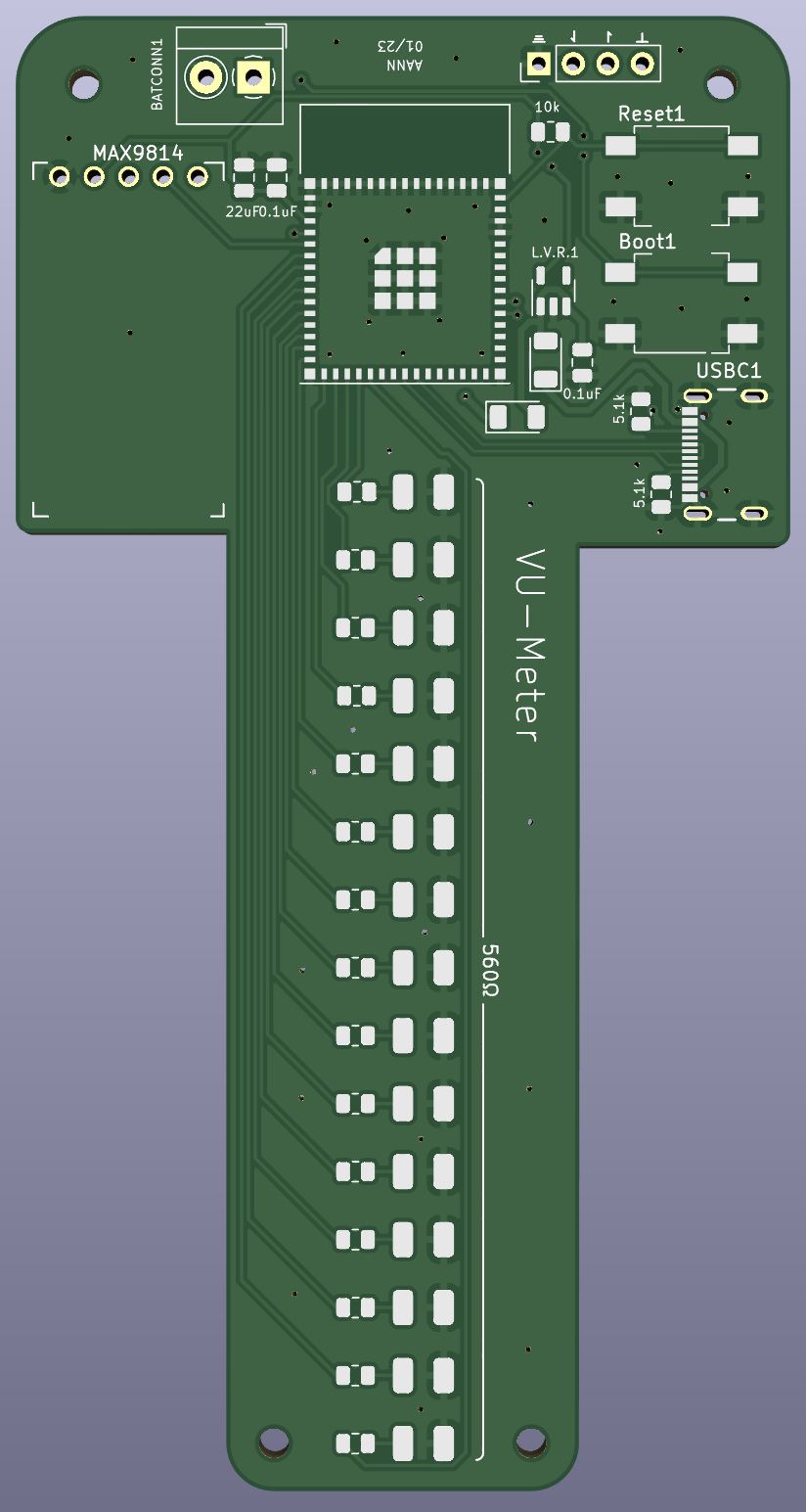
Next you must design the PCB. This is where you can get a bit more creative. I made a T shaped PCB but play around with your design and see if you can come up with something different. Below is my PCB design for reference. (Image below).

Here's the 3D render of the PCB board above.
Order your PCB and soldering
Once you've designed your PCB, you'll have to order it. I ordered mine from JLCPCB. I also ordered a PCB stencil from OSH Stencils since most of my components are SMD components. However, you may use through hole components if you'd like, in which case you wouldn't need the PCB stencil. https://jlcpcb.com/
Once you have all your components, you'll have to solder them onto your PCB.
Coding
Once your board is ready, you'll need to create the code necessary for the VU-Meter to function properly. I'd like this part to be a bit challenging as well, so I will not provide code. However, there are great resources online and a ton of code online at your disposal. I'll remind you that the intention is for the LEDs to react to the sound the mic picks up. Try to create your code in this regard. I'd suggest for you to first test out the mic by itself and write code that outputs the signal it picks up on the serial monitor and the serial plotter. This will give you an idea of how to move forward with the rest of the code.
Since we're using USB-C, we must include the USB library like so.

Another thing to note is that the code for serial communication will be slightly different. You have to add 'USB' in front of any serial command. For example.


3D Casing
You'll also have to create a 3D casing of your choosing in which to place your PCB board. Be creative with your design since there isn't a right way to do this. The purpose of this casing is so you can display the LEDs in whatever way you'd like. When designing this keep in mind you have to power the PCB somehow, either with an external battery like a 9V for example or with a power outlet connection.
Below is a picture of my design. I used SolidWorks but feel free to use your preferred 3D modeling software. I went with something simple and functional but you many show off your 3D modeling skills and create something . more elaborate.

Putting it all together
Once you've uploaded your code on the VU-Meter PCB you'll place to board in the casing and power it.
Reminder
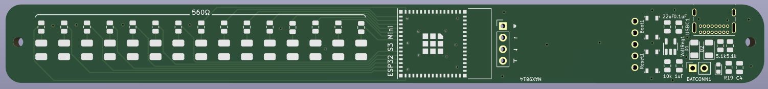
Get creative with your PCB design. I modified the original PCB to make a more narrow, rectangular design. Here it is. I utilized the same components, the only thing I changed was the physical design of the PCB board.
You're ready to get started. Best of luck!