BLYNK Wifi Tutorial
This is a tutorial for using BLYNK, an online service that is perfect for controlling IOT devices like the NodeMCU. This can give you full control of the microcontroller's GPIO pins regardless of where you are as long as you and the microcontroller are connected to the internet.
Materials
- NodeMCU
- LED
- Push Button
Test Circuit
We are going to make a simple test circuit to make sure the fundamentals are working
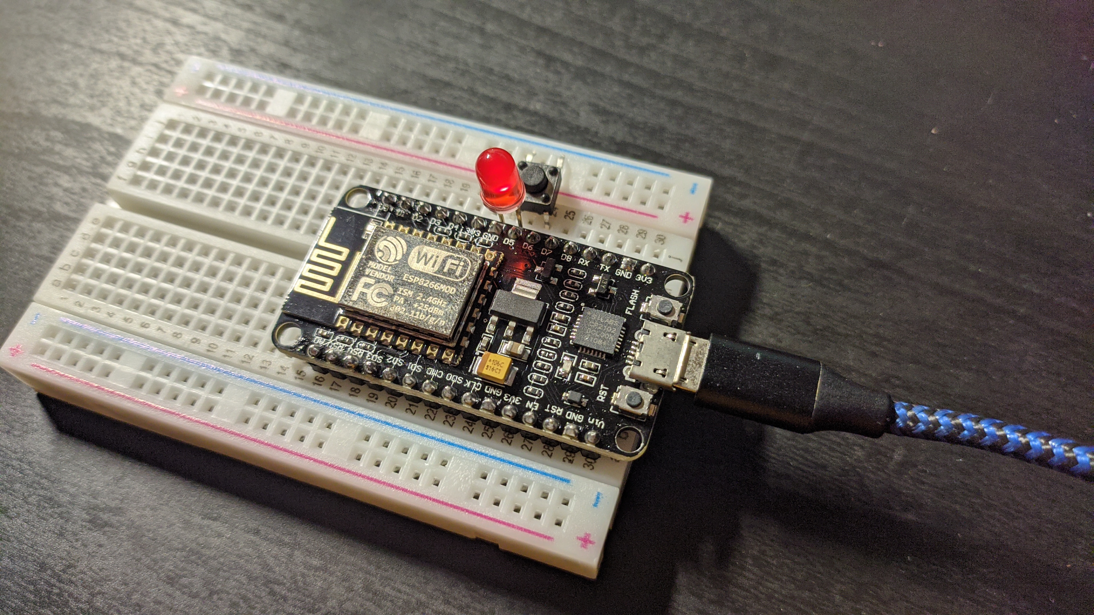
It is a pushbutton attached between GND and D6 and an LED attached to D5
Signing up
Go to the blynk website and make an account
Download the Blynk IOT app onto your phone and log in with your credentials
Making a new Project in Blynk software
Create new template
- On the mobile app, click on the wrench in the top right corner
- Click on the three horizontal bars -> Add template
- Name it whatever "envision tutorial"
- Navigate back to the home page
Creating a new device
- Click on the three horizontal bars in the main menu -> Add New device
- Add a device manually
- Select the envision tutorial template
- Click on the wrench icon while inside of the widget menu to edit the GUI. Add a Button and a labeled display.
Uploading to ESP8266
Getting your credentials
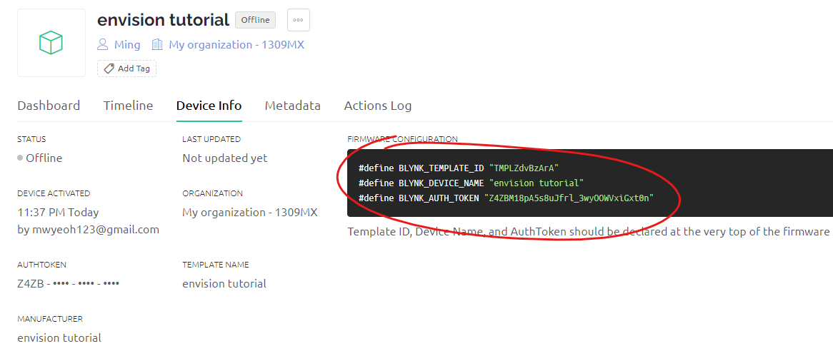
Because BLYNK does not know which microcontroller you want to talk to, you need to assign the microcontroller a certain ID and authentication token. To find this follow these steps:
- Go to blynk cloud on your computer
- Navigate to your device that you want to find information on
- Click on Device Info and copy the section highlighted below
Paste code into Arduino IDE editor. Be sure to install the required libraries. (FastLED and Blynk)
/*************************************************************

  You’ll need:
   - Blynk IoT app (download from App Store or Google Play)
   - ESP8266 board
   - Decide how to connect to Blynk
     (USB, Ethernet, Wi-Fi, Bluetooth, ...)

  There is a bunch of great example sketches included to show you how to get
  started. Think of them as LEGO bricks  and combine them as you wish.
  For example, take the Ethernet Shield sketch and combine it with the
  Servo example, or choose a USB sketch and add a code from SendData
  example.
 *************************************************************/

// Template ID, Device Name and Auth Token are provided by the Blynk.Cloud
// See the Device Info tab, or Template settings
#define BLYNK_TEMPLATE_ID ??
#define BLYNK_DEVICE_NAME ??
#define BLYNK_AUTH_TOKEN ??

// Comment this out to disable prints and save space
#define BLYNK_PRINT Serial


#include <ESP8266WiFi.h>
#include <BlynkSimpleEsp8266.h>
#include "FastLED.h"

char auth[] = BLYNK_AUTH_TOKEN;

// Your WiFi credentials.
// Set password to "" for open networks.
char ssid[] = "wifi name";
char pass[] = "password";

const int LEDpin = D5;
const int buttonPin = D6;

void setup()
{
  // Debug console
  Serial.begin(115200);
  pinMode(BUILTIN_LED, OUTPUT);
  pinMode(LEDpin, OUTPUT);
  pinMode(buttonPin, INPUT_PULLUP);

  digitalWrite(BUILTIN_LED, LOW);
  Blynk.begin(auth, ssid, pass);
  digitalWrite(BUILTIN_LED, HIGH);
}

BLYNK_WRITE(V1) // <- Pin that you would like to read from
{
  // any code you place here will execute when the virtual pin value changes
  Serial.println("Blynk.Cloud is writing something to V1");
  int virtual_pin_value = param.asInt();
  if (virtual_pin_value)
    digitalWrite(LEDpin, HIGH);
  else
    digitalWrite(LEDpin, LOW);
}

void loop()
{
  Blynk.run();
  EVERY_N_MILLISECONDS(100) {
    if (!digitalRead(buttonPin))
      Blynk.virtualWrite(V9, "Button Pressed!");
    else
      Blynk.virtualWrite(V9, "Button Not Pressed!");
  }
  // You can inject your own code or combine it with other sketches.
  // Check other examples on how to communicate with Blynk. Remember
  // to avoid delay() function!
}
Paste in your credentials that you copied at the top of the code. Also be sure to fill in your wifi name and password so that your NodeMCU will actually connect to the internet.
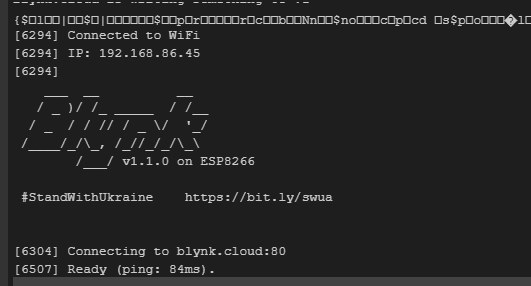
If all goes well, you will see something like this in your Serial monitor to confirm that the microcontroller successfully connected to the internet!
App GUI setting up
Virtual Pins are literally pins that do not exist in the real world. Their only purpose is to communicate information back and forth. We will use these to send the button state information to the MCU and the button state information on the MCU side back to the phone.
While in the editing menu of our GUI, click on the button and set the Data Stream to use V1
Now click on the label and set the Data Stream to use V9
If everything is done correctly, the button on either end will show the correct response on the other end!
Use cases
Wifi controlled garage door opener!
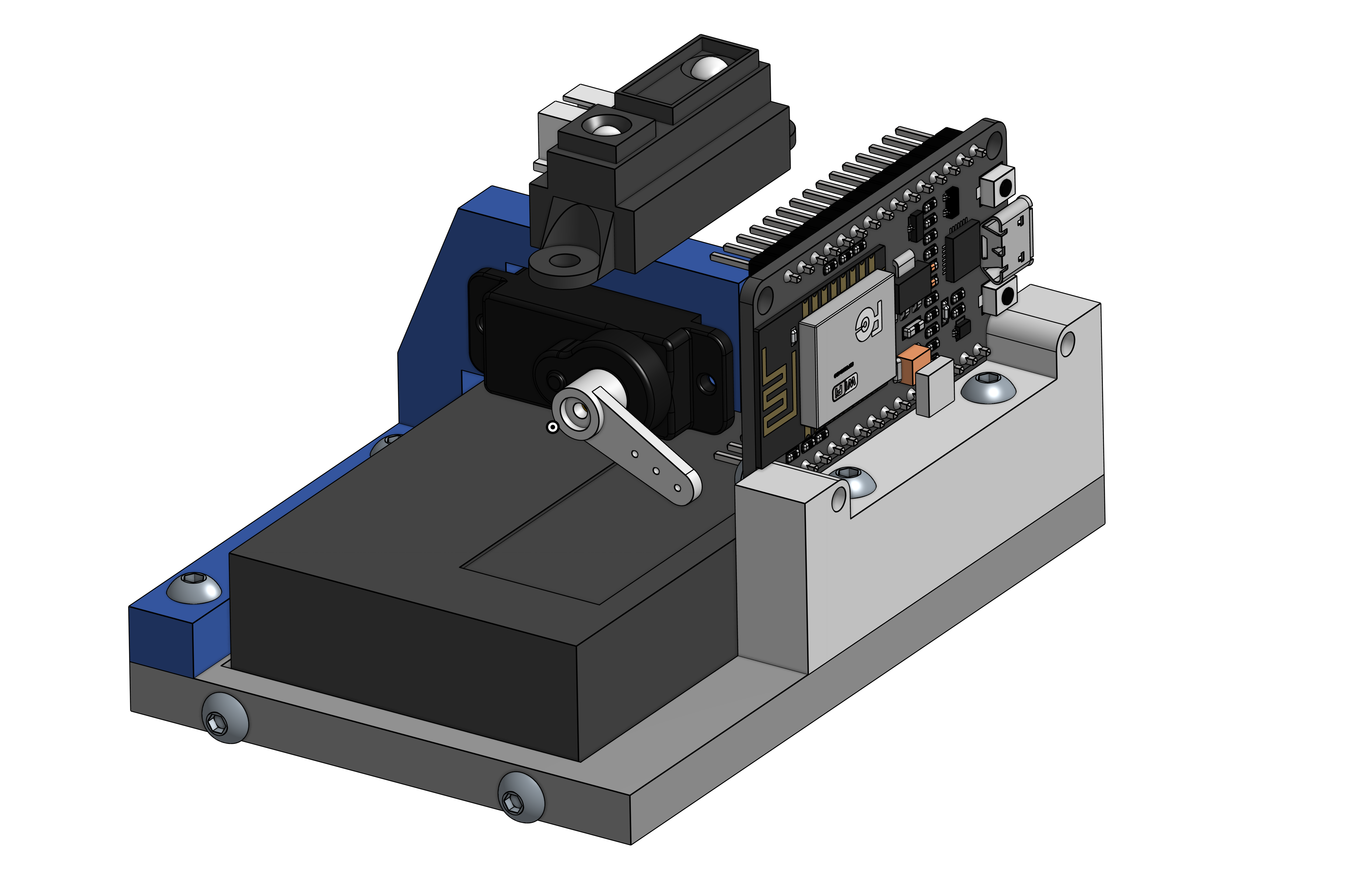
It uses the NodeMCU with a servo arm to give manual control to the user for them to open/close the garage door, as well as automatically with the help of an IR Distance sensor.
Thanks to Blynk, we can create a very powerful remote that can be controlled from anywhere in the world!